Photovoltaic power generation distribution type maximum power output system

A technology for maximum power output and photovoltaic power generation, applied in photovoltaic power generation, light radiation generators, photovoltaic modules, etc., can solve the problems affecting the stability and reliability of the power generation system, affecting the reliability and stability of control, output control and improving control costs and other issues, to achieve the effect of improving self-protection function, easy promotion and application, and simple structure

Inactive Publication Date: 2011-02-02
BEIJING INFORMATION SCI & TECH UNIV
View PDF6 Cites 6 Cited by
  • Summary
  • Abstract
  • Description
  • Claims
  • Application Information

AI Technical Summary

Problems solved by technology

In this structure, the current value and voltage value change during the process of voltage conversion and output power, which causes the photovoltaic modules in the same group to affect each other. It is necessary to obtain the information of adjacent modules, and the adjacent modules will affect each other.
In order to balance the power output of each module, very complex output control is required. The complexity of output control not only increases the control cost, but also seriously affects the reliability and stability of the control, thus affecting the stability and reliability of the power generation system.

Method used


Image

  • Photovoltaic power generation distribution type maximum power output system
  • Photovoltaic power generation distribution type maximum power output system
  • Photovoltaic power generation distribution type maximum power output system

Examples


Embodiment Construction

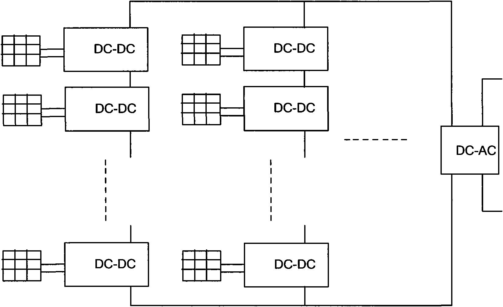
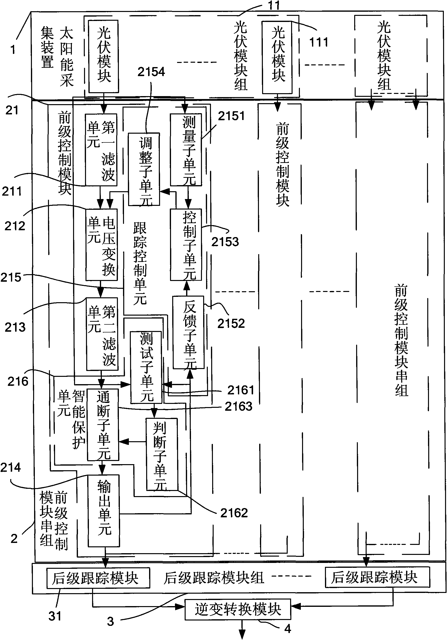
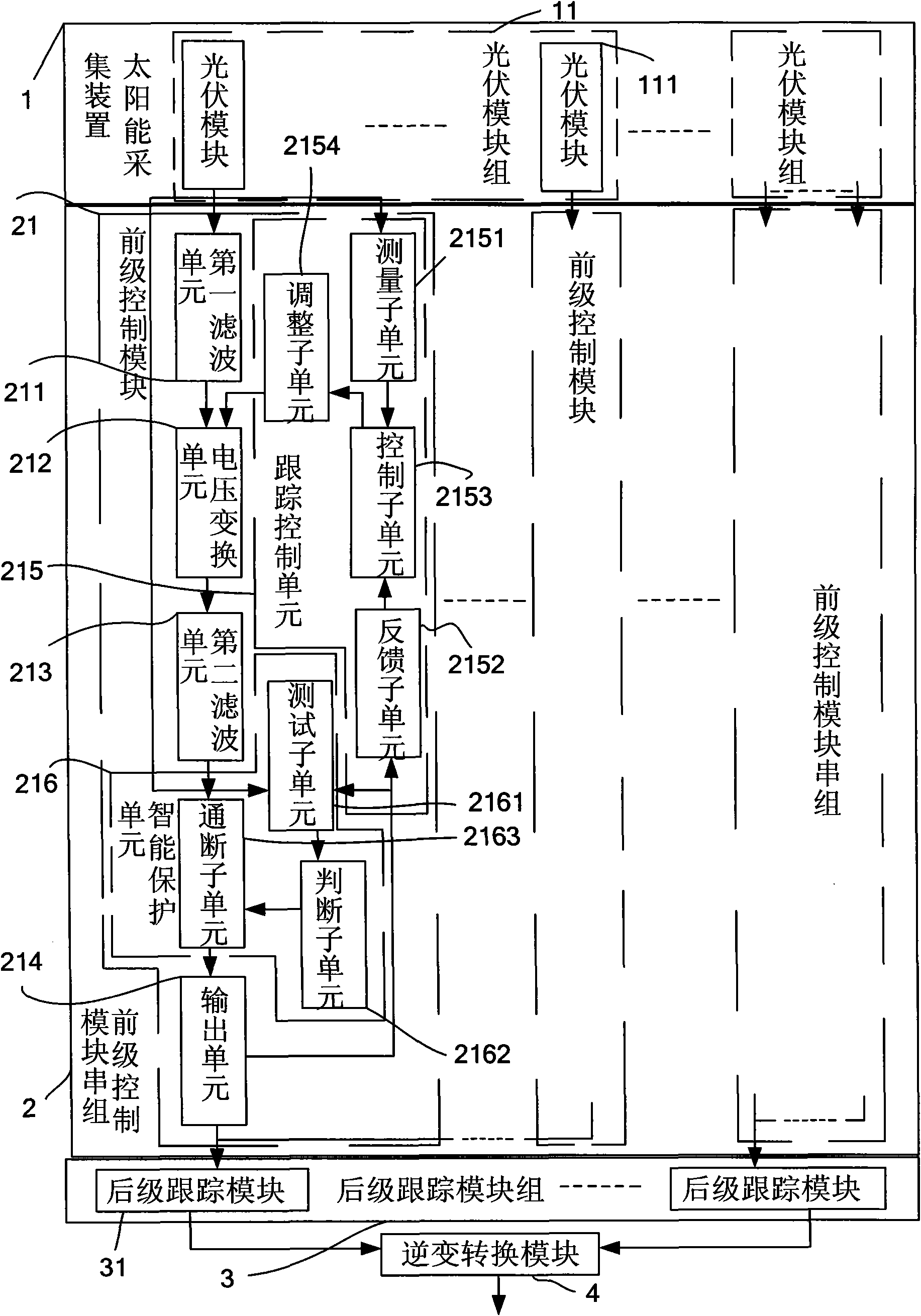
[0034] Such as figure 2 As shown, the present invention includes a solar energy collection device 1 , a front-stage control module string group 2 , a rear-stage control module group 3 and an inverter conversion module 4 . The solar energy harvesting device 1 is used to collect solar energy. It achieves the maximum power output through the two-stage control of the front-stage control module string group 2 and the rear-stage control module group 3 , and then performs current output through the inverter conversion module 4 after current conversion.

[0035] The solar energy harvesting device 1 includes more than two sets of photovoltaic module groups 11, each photovoltaic module 111 in the photovoltaic module group 11 is connected with a front-end control module 21, and the photovoltaic module 111 collects solar energy and converts the solar energy into DC power and sends it to the front-end control Module 21.

[0036] The front-end control module string group 2 includes more t...


PUM


Abstract

The invention provides a photovoltaic power generation distribution type maximum power output system, which comprises a solar energy collection device, a forestage control module series set, a backstage control module set and an inverse conversion module, wherein the solar energy collection device comprises more than two groups of photovoltaic modules which collect solar energy, convert the solarenergy into direct current power and send the direct current power to forestage control modules; the forestage control module series set comprises more than two groups of forestage control modules which correspond to the photovoltaic modules one by one and are connected in series, and the forestage control modules convert a voltage and then output an electric current to backstage control modules;the backstage control module set comprises more than two backstage control modules which are connected in parallel, and the backstage control modules perform direct current voltage conversion and send the conversion result to the inverse conversion module; and the inverse conversion module outputs the electric current. In the invention, a current and voltage two-stage control mode is adopted, thecontrol structure eliminates influences on adjacent modules, the photovoltaic modules in the same group have no influences on one another and are not required to acquire the information of the adjacent modules, so that the output control of the module is simplified, the control over the power output and the stability and reliability of the power generation system are improved.

Description

technical field [0001] The invention relates to a photovoltaic power generation distributed maximum power output system. Background technique [0002] The basic unit of a photovoltaic power generation system is a photovoltaic module. The photoelectric characteristics of photovoltaic modules are nonlinear, and there are peaks in their power curves. Therefore, a large number of maximum power point tracking (MPPT) methods have been proposed to ensure the maximum power output of photovoltaic modules. A photovoltaic system consists of multiple photovoltaic modules connected in series and parallel to form a photovoltaic array. Under uniform light conditions, the power curves of each photovoltaic module are consistent, and the power curve of the photovoltaic array has a unique peak. Under partial shade conditions, the power curves of each photovoltaic module are different, and the power curve of the photovoltaic array appears multi-peak phenomenon. At this time, the photovoltaic...

Claims


Application Information

Patent Timeline
Patent Type & Authority Applications(China)
IPC IPC(8): H02N6/00G05F1/67H02S40/30
CPCY02E10/58Y02E10/56
Inventor 乔道鄂徐小力
Owner BEIJING INFORMATION SCI & TECH UNIV
Why Eureka
Try Eureka