Quick-spliced sectional type composite material truss bridge

A composite material and truss bridge technology is applied in the field of rapid assembly of segmented composite material truss bridges. , Broad application prospects, the effect of saving maintenance costs

Inactive Publication Date: 2011-02-09
NANJING UNIV OF TECH
View PDF9 Cites 21 Cited by
  • Summary
  • Abstract
  • Description
  • Claims
  • Application Information

AI Technical Summary

Problems solved by technology

[0002] The development of bridges has a long history. We often see wooden bridges, stone bridges, reinforced concrete bridges and steel structure bridges. Wooden bridges are generally used for footpath bridges because of their low bearing capacity, poor overall performance, and poor durability. , so its span and application range are limited; the characteristics of the stone bridge itself determine its limitations; reinforced concrete bridges and steel structure bridges are mostly used for road bridges and railway bridges, which can have larger spans and bear larger loads. They have irreplaceable advantages, but they also have their own insurmountable defects, such as the weight of reinforced concrete bridges, long construction period, poor corrosion resistance, difficulties in bridge maintenance and protection, etc.

Method used


Image

  • Quick-spliced sectional type composite material truss bridge
  • Quick-spliced sectional type composite material truss bridge
  • Quick-spliced sectional type composite material truss bridge

Examples


Embodiment 1

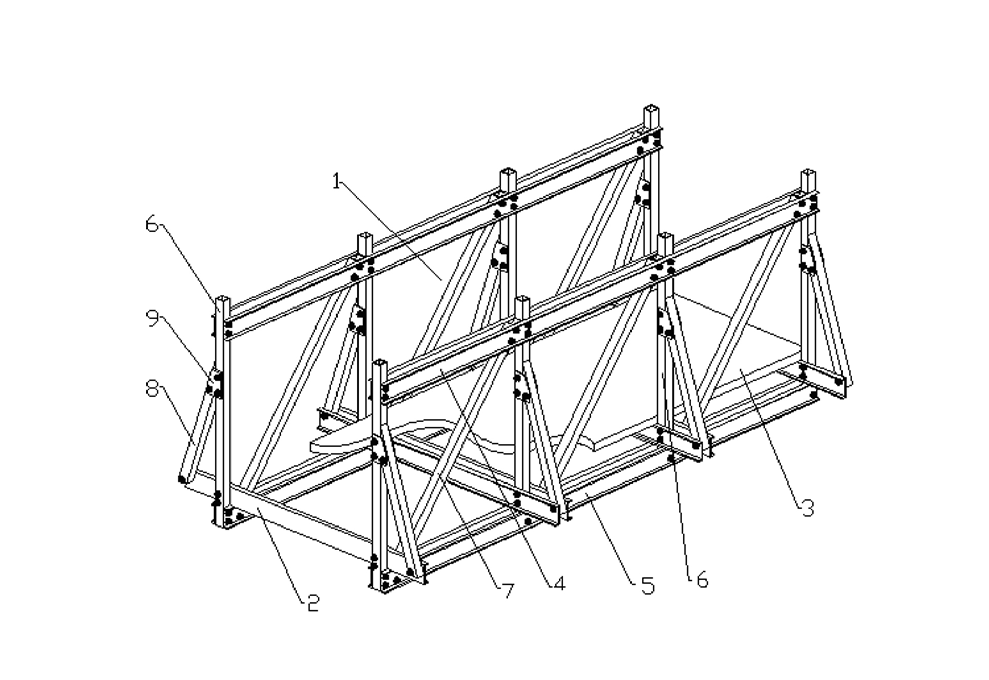
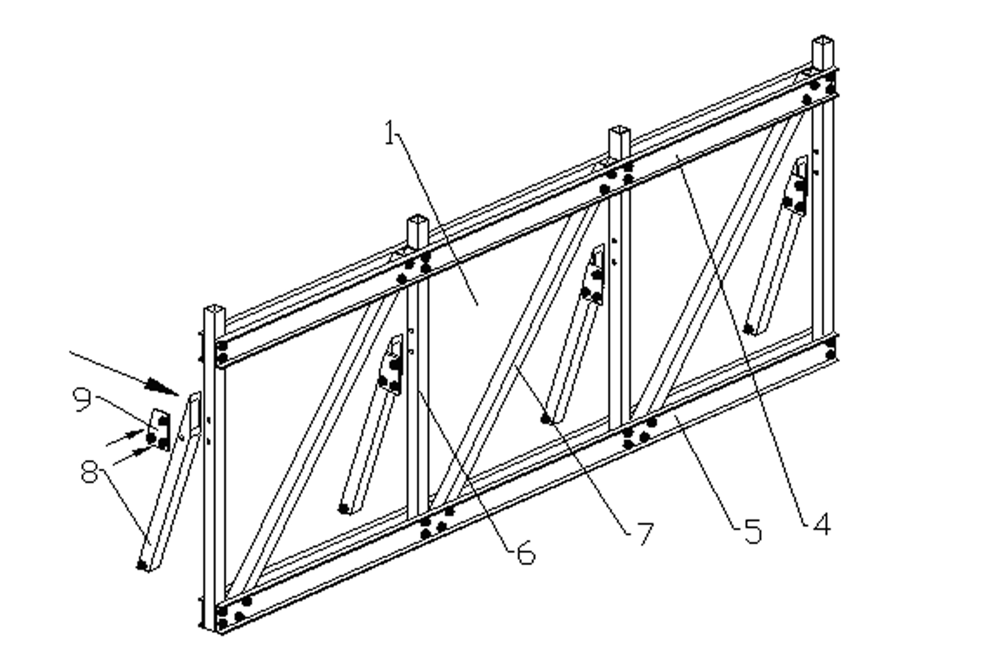
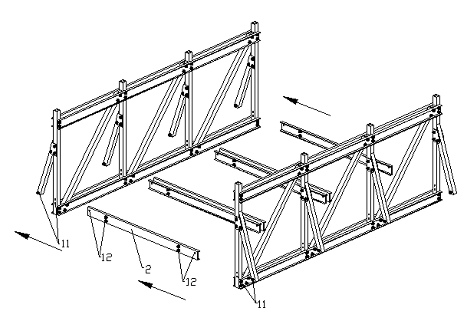
[0033] Depend on Figure 1-5 As shown, the rapid assembly segmented composite truss bridge of the present invention is made up of a facade truss 1, a beam 2 and a bridge deck 3, consisting of figure 2 It can be seen that the upper string girder 4, the lower string girder 5, the vertical web girder 6 and the inclined web girder 7 are fixed by bolts to form a facade truss 1. The two ends are fixedly connected, the inclined web beams 7 are obliquely placed between two adjacent vertical web beams 6 and the upper and lower ends of the inclined web beams 7 are respectively fixedly connected with the upper string beam 4 and the lower string beam 5; The structural strength is fixedly connected with the outer support beam 8 through the outer gusset plate 9 on the outer side of the vertical web beam 6 . Depend on image 3 It can be seen that by figure 2 As shown, two mutually symmetrical façade trusses 1 and beams 2 are assembled, and the beams 2 are installed on the bottom chord 5...

Embodiment 2

[0036] Depend on Figure 6-7 As shown, when the rapid assembly segmented composite truss bridge of the present invention needs to bear the vehicle load, a slightly shorter beam 2 can be used to replace the beam shown in Embodiment 1 with both ends exceeding a part of the width of the façade truss 1 2. Remove the outer support beam 8 and outer gusset plate 9 provided on the truss bridge unit in Example 1, and fix the bolts 11 on the vertical web beam 6 to the bolt holes 12 on the crossbeam 2 on the upper chord 4 connected to form a box truss bridge unit. In practical applications, the Figure 6The bridge deck 3 is laid on the box-shaped upper surface of the box-shaped truss bridge unit shown and spliced ​​together in the transverse direction to form Figure 7 The above-supported vehicle-mounted bridge shown. The length and width of the above-supported vehicle-mounted bridge can be assembled according to actual needs.

Embodiment 3

[0038] Depend on Figure 8 As shown, when some places only need pedestrian bridges as common bridges or emergency bridges, it can be used Figure 6 Based on the box-shaped truss bridge unit shown, an oblique support beam 13 is added between the beams 2 on the upper surface of the truss bridge unit to form a closed box-shaped structure, and the bridge deck 3 is laid on the lower surface of the truss bridge unit. On the crossbeam 2, a down-bearing pedestrian bridge is formed, and an awning can be laid on the closed box-shaped top surface to form a Figure 8 As shown in the through-type footbridge, the length of the under-type footbridge can be assembled according to actual needs. In addition, it is also possible to use figure 1 The truss bridge element shown, in figure 1 In the shown truss bridge unit, a crossbeam 2 and an oblique support beam 13 are added above the upper chord 4, and the crossbeam 2 on the upper chord 4 should be slightly shorter than the crossbeam 2 on the ...


PUM


Abstract

The invention relates to a quick-spliced sectional type composite material truss bridge which comprises facade trusses (1), cross beams (2) and bridge decks (3), wherein each facade truss (1) is composed of an upper chord beam (4), a lower chord beam (5), vertical web girders (6) and inclined web girders (7); the upper chord beam (4) and the lower chord beam are arranged in parallel on the facade and respectively fixed with the upper and lower ends of each vertical web girder (6); each inclined web girder (7) is slantly arranged between every two adjacent vertical web girders (6), and the upper and lower ends of each inclined web girder (7) are respectively fixed with the upper chord beam (4) and the lower chord beam (5); both ends of each cross beam (2) are respectively fixed with two vertical web girders (6) parallel to the facade trusses (1) on the corresponding sides; and each bridge deck (3) is arranged on each cross beam (2) to constitute a truss bridge unit. The invention applies fiberglass reinforced plastics to the entire truss bridge and adopts flexible sectional type design, thus, the invention has the advantages of light weight, shock resistance, corrosion resistance, and convenient and quick transportation and assembly, and has wide application prospects in emergency rescue.

Description

technical field [0001] The invention relates to the field of bridge applications, in particular to a lightweight composite truss bridge that is mainly used in the fields of walkway bridges and emergency bridges and can be quickly assembled, in particular to a rapidly assembled segmented composite truss bridge. Background technique [0002] The development of bridges has a long history. We often see wooden bridges, stone bridges, reinforced concrete bridges and steel structure bridges. Wooden bridges are generally used for footpath bridges because of their low bearing capacity, poor overall performance, and poor durability. , so its span and application range are limited; the characteristics of stone bridges determine its limitations; reinforced concrete bridges and steel structure bridges are mostly used for road bridges and railway bridges, which can have larger spans and bear larger loads. They have their irreplaceable advantages, but they also have their own insurmountabl...

Claims


Application Information

Patent Timeline
Patent Type & Authority Applications(China)
IPC IPC(8): E01D6/00
Inventor 刘伟庆方海徐以扬陆伟东
Owner NANJING UNIV OF TECH
Why Eureka
Try Eureka