LED illumination light source device using LED complementary color light

A technology of LED lighting and light source device, which is applied to lighting devices, components of lighting devices, light guides of lighting systems, etc., can solve the problems of poor reliability, poor reliability, and reduced luminous efficiency of mixed phosphor technology, so as to avoid low luminescence Efficiency issues, high reliability, high efficiency effects

Active Publication Date: 2011-02-09
QINGDAO O MEC MEDICAL TECH
View PDF5 Cites 12 Cited by
  • Summary
  • Abstract
  • Description
  • Claims
  • Application Information

AI Technical Summary

Problems solved by technology

Although a high color rendering index can be achieved by mixing a variety of phosphors, the luminous efficiency will be reduced by about 50%, and the reliability of the mixed phosphor technology is still relatively poor, especially under large driving current densities, such as per mm 2 If the driving current density of the light-emitting chip is greater than 1A, the reliability will be even worse

Method used


Image

  • LED illumination light source device using LED complementary color light
  • LED illumination light source device using LED complementary color light
  • LED illumination light source device using LED complementary color light

Examples


Embodiment 1

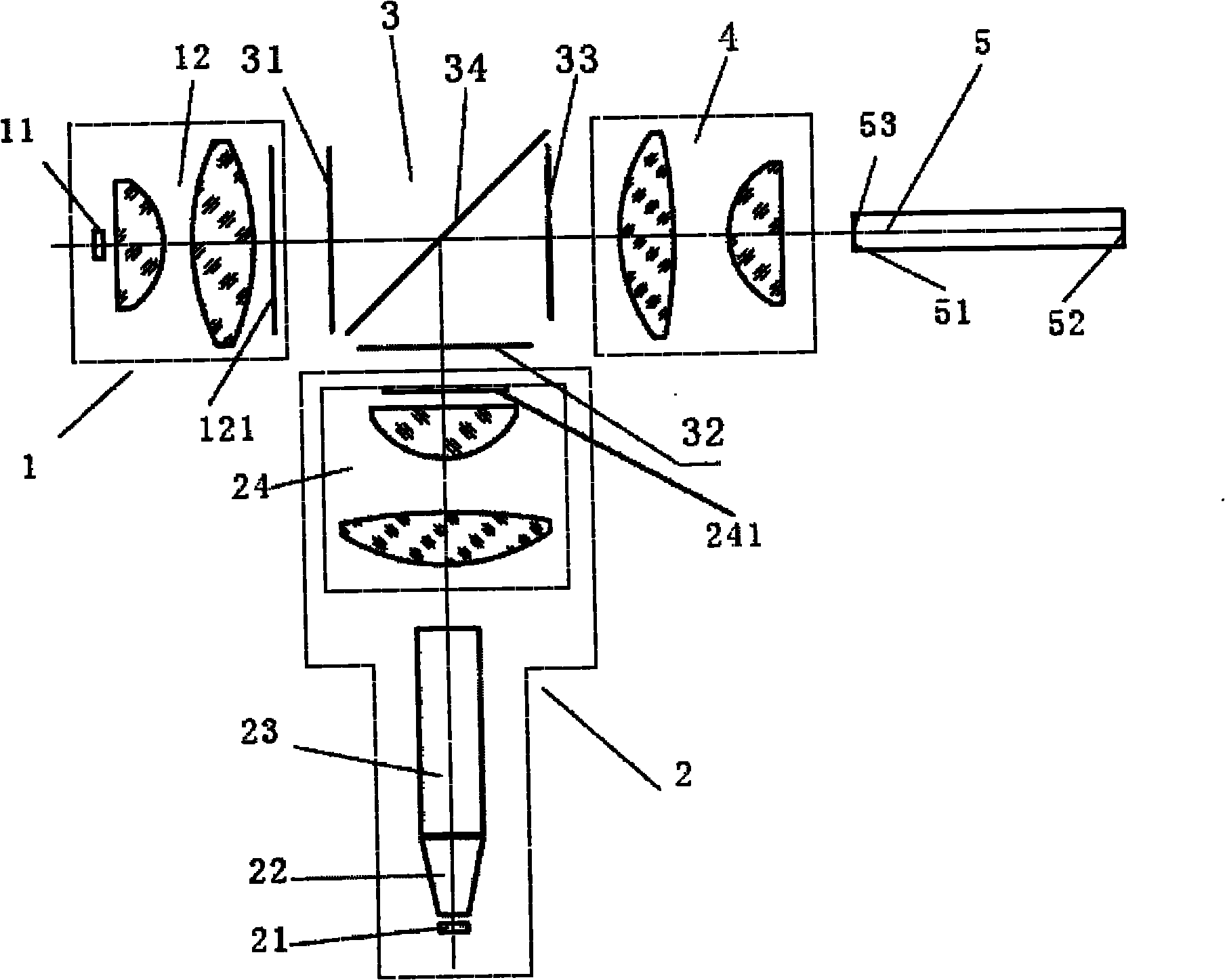
[0022] In this embodiment, except that the color combiner 3 is a glued prism, the remaining parts have the same figure 2 The structure shown is exactly the same, the following is its key technical data:

[0023] The white LED light-emitting chip array 11 includes nine white LED light-emitting chips, which are arranged in a 3×3 matrix. The size of each white LED light-emitting chip is 1mm×1mm, and the distance between adjacent chips is 0.1mm. The white light collection optics Component 12 is a lens group, and the focal length of the lens group is 12mm;

[0024] Complementary color LED light-emitting chip array 21 includes four complementary color LED light-emitting chips, arranged in a 2×2 matrix, of which there are two blue light LED light-emitting chips, two red light LED light-emitting chips, and each complementary color LED light-emitting chip The size is 1mm×1mm, and the distance between adjacent chips is 0.1mm. The green LED light emitting chips and the red light LED li...

Embodiment 2

[0035] This embodiment has the same figure 2 The structure shown is exactly the same, the following is its key technical data:

[0036] The color combiner 3 is a plane color combiner with a size of 28mm×40mm×1mm. In addition, the rest of the technical data are exactly the same as those of the first embodiment.

Embodiment 3

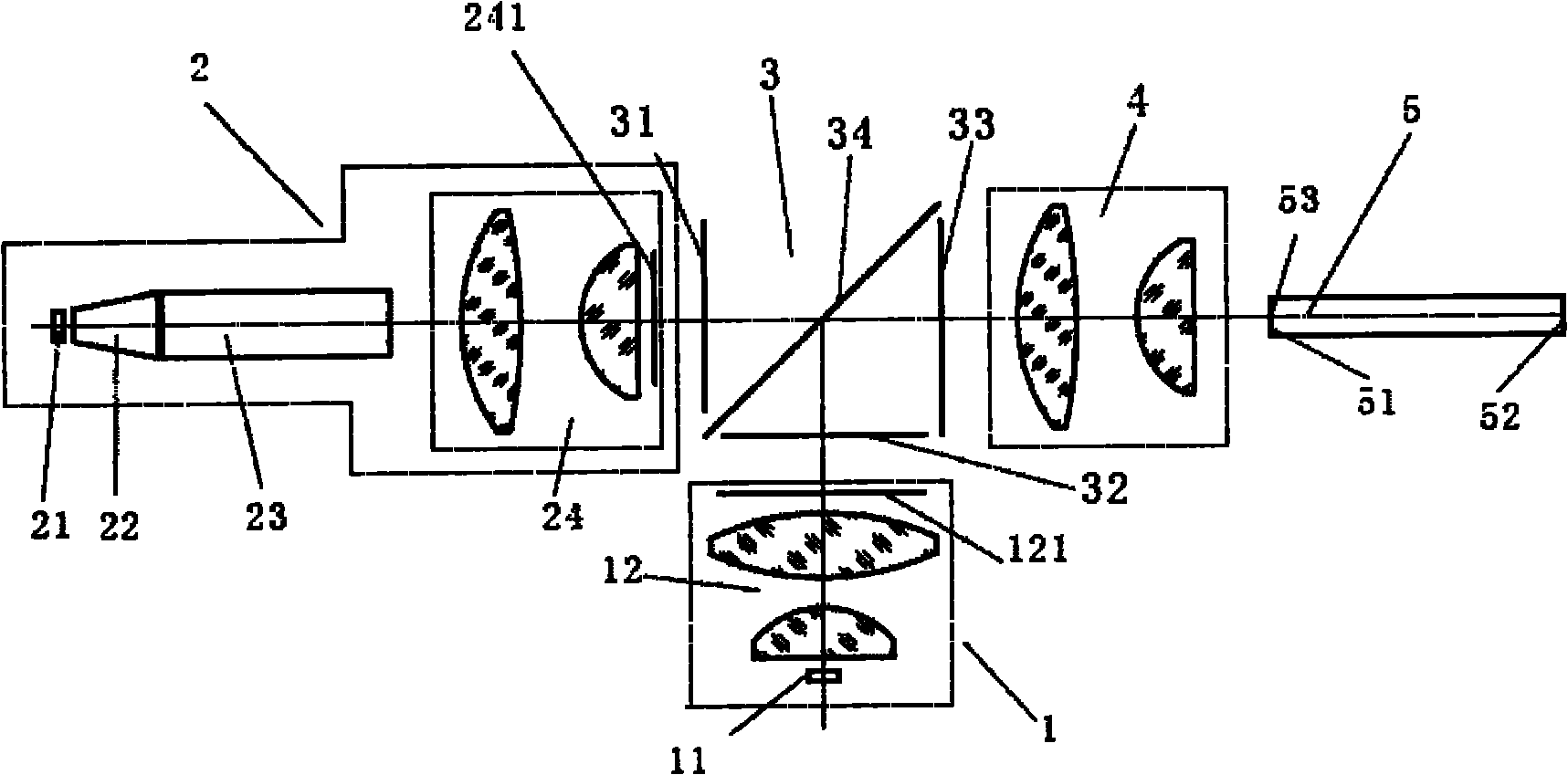
[0038] This embodiment has the same image 3 The structure shown is exactly the same, the following is its key technical data:

[0039] The white LED light-emitting chip array 11 includes nine white LED light-emitting chips, which are arranged in a 3×3 matrix. The size of each white LED light-emitting chip is 1mm×1mm, and the distance between adjacent chips is 0.1mm. The white light collection optics Component 12 is a lens group, and the focal length of the lens group is 12mm;

[0040] Complementary color LED light-emitting chip array 21 includes four complementary color LED light-emitting chips, arranged in a 2×2 matrix, of which there are two blue light LED light-emitting chips, two red light LED light-emitting chips, and each complementary color LED light-emitting chip The size is 1mm×1mm, and the distance between adjacent chips is 0.1mm. The green LED light emitting chips and the red light LED light emitting chips are arranged in different rows and different columns in th...


PUM


Abstract

The invention relates to an LED illumination light source device using LED complementary color light, which can realize illumination light source with a high color rendering index and belongs to the technical field of semiconductor illumination. Based on the known white light LED illumination light source device, a complementary color light luminous chip which is packaged by mixing a blue light LED luminous chip and a red light LED luminous chip is introduced, white light emitted by a white light LED luminous chip and the complementary color light emitted by the complementary color light luminous chip are synthesized into the white light with the high color rendering index through a color combining device, and the white light is coupled to an incident surface of an optical fiber through afocus coupling optical component and output through an emergent surface of a light-transmission optical fiber. The LED illumination light source device has the advantages of high color rendering index (the color rendering index reaches more than 90) and high reliability and efficiency without increasing optical extended amount of a white light source, and is particularly suitable for a system, such as endoscopes, surgical operation microscopes, and the like, which requires high color rendering index, has limited optical extended amount and is based on an optical fiber transmission illumination ray.

Description

technical field [0001] The invention relates to an LED lighting source device using LED complementary color light, which can realize a high color rendering index lighting source, and belongs to the technical field of semiconductor lighting. Background technique [0002] With the continuous improvement of luminous efficiency, white LEDs are more and more widely used. There are two main types of existing white LED lighting sources: one uses white LEDs as illuminants, white LEDs are blue LEDs coated with yellow-emitting phosphors that can be effectively excited by blue light, and blue LEDs emit blue light. A part is absorbed by the phosphor, which excites the phosphor to emit yellow light, and the remaining part is mixed with the emitted yellow light, and their intensity ratio is adjusted to obtain white light with various color temperatures; the other is to combine red, green and blue LEDs to emit Red, green and blue light mix to form white light. Compared with traditional l...

Claims


Application Information

Patent Timeline
Patent Type & Authority Applications(China)
IPC IPC(8): F21S2/00F21V17/00F21V19/00F21V8/00F21Y101/02
Inventor 辜长明郑安民郑耀
Owner QINGDAO O MEC MEDICAL TECH
Why Eureka
Try Eureka