Prerecording method used for monitoring equipment

A monitoring equipment and pre-recording technology, which is applied in the directions of digital recording/reproduction, color TV parts, and TV system parts, etc., can solve the problems of less pre-recording time, short pre-recording time, and occupying hard disk storage space. , to achieve the effect of improving the technical level, large capacity and low cost

Inactive Publication Date: 2011-02-09
SHENZHEN INFINOVA
View PDF3 Cites 28 Cited by
  • Summary
  • Abstract
  • Description
  • Claims
  • Application Information

AI Technical Summary

Problems solved by technology

However, even if this is done, it still cannot meet the needs, because different audio and video streams occupy different spaces. For example, the QCIF video stream of 64k per second can meet the pre-recording of more than 30 seconds; the D1 video of 1.25Mbit per second Stream, the maximum can basically meet the pre-recording of nearly 12 seconds, if the bit rate is higher, the pre-recording time is less
In high-bit rate audio and video storage devices, often only 1-2 seconds of pre-recording can be achieved, which cannot meet the needs at all
And the continued expansion of the pre-recording memory is obviously not a solution to the short pre-recording time.
[0004]Due to the short duration of pre-recording, many monitoring devices do not use pre-recording, but real-time recording
Since the real-time video is recorded in the whole process, it is not easy to find when the manager calls the video record, and the real-time video will take up a lot of hard disk storage space

Method used


Image

  • Prerecording method used for monitoring equipment
  • Prerecording method used for monitoring equipment
  • Prerecording method used for monitoring equipment

Examples


Embodiment Construction

[0043] In order to fully understand the technical content of the present invention, the technical solutions of the present invention will be further introduced and illustrated below in conjunction with specific examples, but not limited thereto.

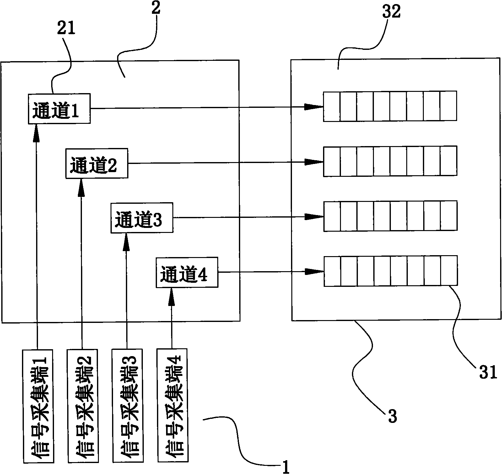
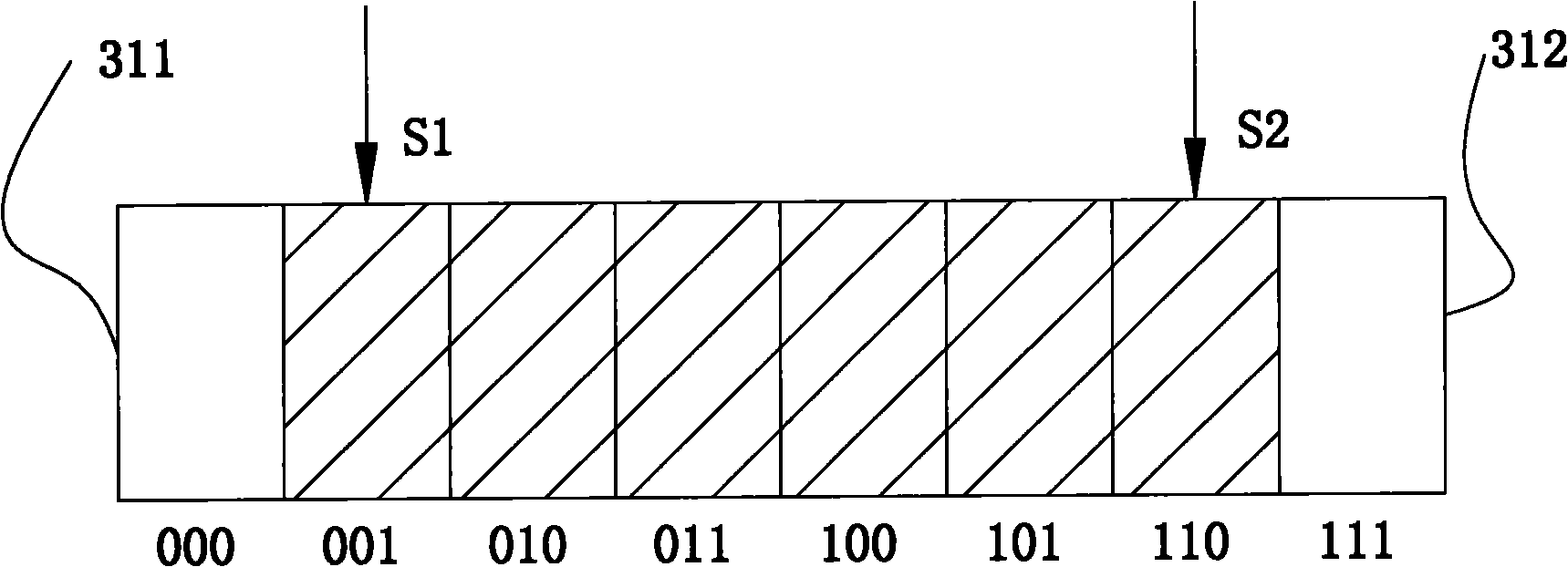
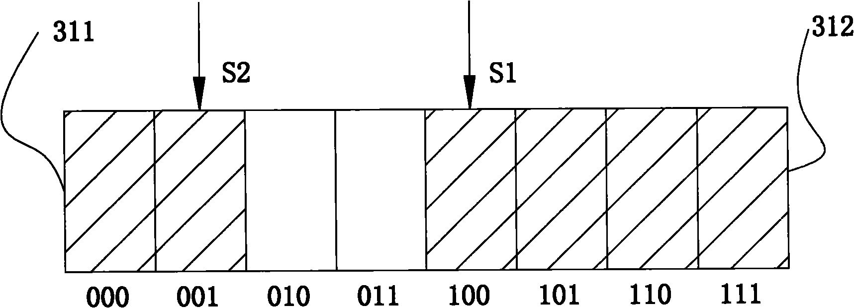
[0044] Such as Figure 1 to Figure 3 As shown, the present invention is used for the pre-recording method of monitoring equipment, and this method is in the monitoring equipment (comprising the signal acquisition end of gathering sound, video signal usually, and comprising CPU, internal memory, hard disk, main frame and display screen etc. of main board) The hard disk storage 3 is provided with a common storage area 32 and a pre-recorded storage area 31, and the data processing unit 2 of the monitoring equipment (usually referring to the CPU, internal memory and mainboard of the monitoring equipment) passes the real-time signal of the signal acquisition terminal 1 through the data of the monitoring channel 21 After being processed into...


PUM


Abstract

The invention discloses a prerecording method used for monitoring equipment. A hard disc memory of the monitoring equipment is provided with a command storage area and a prerecording storage area. The prerecording method comprises the following steps that: a data processing unit of the monitoring equipment performs data processing on real-time signals acquired by a signal acquisition end to obtain monitoring signals, and stores the monitoring signals from a starting section of the prerecording storage area to a stop section of the prerecording storage area in turn; when the prerecording area is full, the data processing unit stores the monitoring signals from the starting section to the stop section one by one again in a coverage way; and when the monitoring equipment enables a conventional recording function, the data processing unit writes prerecording signals in the prerecording storage area into the common storage area as a starting part of the recording file first, and then continuously writes the monitoring signals recorded in real time into the common storage area. The method of the invention can fully utilize the characteristics of large capacity of a hard disc and a plurality of monitoring channels can be arranged on one set of monitoring equipment so as to fulfill the aim of low-cost monitoring. The popularization and the application of the method can effectively improve the technical level of the monitoring equipment.

Description

technical field [0001] The invention relates to a pre-recording method for collecting real-time signals by a computer, in particular to a pre-recording method for monitoring equipment, which can realize long-time pre-recording of real-time monitoring signals. Background technique [0002] In the prior art, pre-recording has appeared on monitoring equipment (mainly security monitoring equipment) as a basic function. Events such as prying doors are detected by the vibration sensor), the recording function is started, and the content of a period of time before the event can also be recorded into the video file. The traditional method is: open up a section of memory (2Mbyte or more) for each monitoring channel. Before the event occurs, the compressed data stream (which can be audio stream and / or video stream) of each channel is continuously written into this memory, and when the event occurs and the real-time recording is prepared, the pre-recorded data in this memory is append...

Claims


Application Information

Patent Timeline
Patent Type & Authority Applications(China)
IPC IPC(8): G11B20/10H04N5/781
Inventor 谢君华廖恒斌
Owner SHENZHEN INFINOVA
Why Eureka
Try Eureka