Threaded rod of injection molding machine with reversely connected threaded rod head

A technology of screw and screw head of injection molding machine, applied in the field of injection molding screw, can solve the problem of low durability of injection molding machine

Inactive Publication Date: 2011-02-16
BEIJING UNIV OF CHEM TECH
View PDF10 Cites 2 Cited by
  • Summary
  • Abstract
  • Description
  • Claims
  • Application Information

AI Technical Summary

Problems solved by technology

And a screw that is not straight will produce greater wear during the high tempe

Method used


Image

  • Threaded rod of injection molding machine with reversely connected threaded rod head
  • Threaded rod of injection molding machine with reversely connected threaded rod head
  • Threaded rod of injection molding machine with reversely connected threaded rod head

Examples


Embodiment Construction

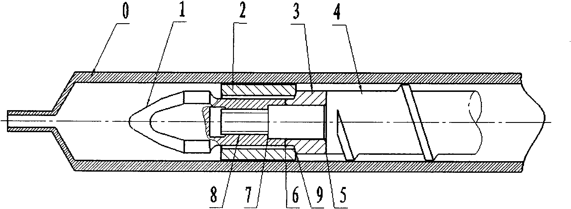
[0018] The injection molding machine screw of the present invention is mainly composed of the following parts: screw head 1 , check ring 2 , thrust ring 3 , and screw body 4 . The front end of the screw body has a section of smooth small-diameter cylinder 6 and a section of stud 8 in turn, and 7 is a stepped surface, and the thrust ring and the screw body are positioned on the contact surface 5 . The external screw thread 8 of the stud matches the internal screw hole of the screw head to connect the two parts, which can have higher straightness and coaxiality.

[0019] Such as figure 1 As shown, when the screw of the injection molding machine injects the material forward. The non-return ring and the thrust ring are closed at the contact surface 9. Since the material is sealed in the storage section in the barrel 0, the screw moves forward, the nozzle 16 is opened, and the material is injected into the mold through the flow channel.

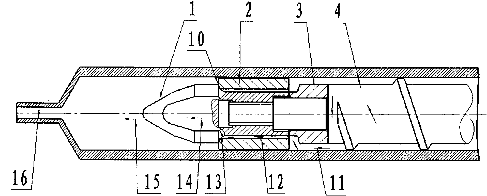
[0020] Such as figure 2 As shown, when ...


PUM


Abstract

The invention relates to a threaded rod of an injection molding machine with a reversely connected threaded rod head, which mainly comprises a threaded rod body, a thrust ring, a check ring and a threaded rod head. The front end of the threaded rod body is provided with a smooth cylinder with a small diameter and a small stud in order, and the stud is matched with an internal threaded hole in the threaded rod head to connect the stud with the threaded rod head. Therefore, the threaded rod has high linearity and concentricity. The thrust ring is sheathed on the smooth cylinder with a small diameter, and the front end surface and the rear end surface of the thrust ring are respectively abutted with the rear end surface of the threaded rod head and the front end surface of the threaded rod. When the stud at the front end of the thread rod is screwed into the internal threaded hole in the threaded rod head by a certain depth, the thrust ring is axially fixed. The thrust ring has different outside diameters according to different requirements for materials and processes so as to generate different backpressure. The annular check ring is installed on a cylinder of the threaded rod head between the thrust ring and the threaded rod head, can rotate freely and can move back and forth. When the rear side surface of the check ring is not fully abutted with the front diagonal side surface of the thrust ring, fusant plasticized in a threaded groove is pressed into a storage section through the clearance, another clearance formed between the cylinder of the threaded rod head and a charging barrel as well as a threaded rod head groove. However, when the rear side surface of the check ring is abutted with the front diagonal side surface of the thrust ring, the fusant in the storage section is prevented from back flowing to the threaded groove, thus playing a role of sealing, and the threaded rod can be injected.

Description

technical field [0001] The invention relates to an injection molding screw used in an injection molding machine. Background technique [0002] Injection screw is one of the key parts of injection molding machine. It rotates in the barrel of the injection molding machine. Its main function is to melt and plasticize the solid polymer particles or powder, store and measure, and then inject a certain amount of melt stored into the mold. After the mold is cooled, it is ejected to obtain plastic products. [0003] The screw with ring check screw head in injection molding screw consists of the following parts: screw head, check ring, thrust ring and screw body. The non-return ring is located between the screw head and the thrust ring, and is wrapped on the cylindrical section of the screw head; the inner diameter of the anti-reverse ring and the outer diameter of the screw head cylinder form the flow path of the material, and the outer diameter forms the inner diameter of the barr...

Claims


Application Information

Patent Timeline
IPC IPC(8): B29C45/60
Inventor 王克俭
Owner BEIJING UNIV OF CHEM TECH
Why Eureka
Try Eureka