Turbulent bar structure for drying cylinder with functions of high efficiency and energy saving

A technology for spoiler rods and drying cylinders is applied in the field of spoiler rod structures for high-efficiency and energy-saving drying cylinders, which can solve the problem of unreasonable number and size of strip spoiler rods, poor paper drying effect, and increase the production cost of manufacturers. and other problems, to achieve the effect of scientific and reasonable number and size, simple structure, and reduced energy consumption

Inactive Publication Date: 2012-07-25
JIAOZUO CHONGYI LIGHT IND MACHINERY
View PDF0 Cites 0 Cited by
  • Summary
  • Abstract
  • Description
  • Claims
  • Application Information

AI Technical Summary

Problems solved by technology

However, the cross-section of the more commonly used strip spoiler is square or rectangular, and the hollow structure has high thermal resistance, and there is a gap between it and the inner wall of the cylindrical cylinder, and the fit is not tight, which also improves the thermal resistance. In addition, there are unreasonable problems in the number and size of the bar-shaped spoiler rods. There will be "overflow" of condensed water over the spoiler rods. "Overflow" will also increase the thermal resistance, causing the surface of the dryer to drop in temperature
[0004] In summary, the effect achieved by combining the spoiler rod structure and the siphon device in the prior art is as follows: Figure 10 As shown, the curves marked with "20 hollow spoiler rods", "25 hollow spoiler rods" and "30 hollow spoiler rods" are the temperature changes of structures used in the prior art at different speeds The "no spoiler rod" curve is the temperature change curve after the water film is formed in the dryer. Through comparison, it can be known that when the dryer cylinder changes from low speed to high speed when the spoiler rod is used, due to the existence of condensed water The temperature change is very obvious. The temperature drop is 4-7°C. When the speed is greater than 1200m / min, the spoiler has failed. This is very unfavorable for the drying of the paper. When the drying effect of the paper is not good, it will It leads to quality problems of the final product. Therefore, in the production process using the existing spoiler structure, the temperature of the steam must be continuously increased or the rotation speed of the drying cylinder must be reduced to meet the normal work requirements. This will inevitably cause a lot of waste of energy and increase the production capacity of manufacturers The production cost reduces the production efficiency and is not conducive to ensuring the quality of the paper

Method used


Image

  • Turbulent bar structure for drying cylinder with functions of high efficiency and energy saving
  • Turbulent bar structure for drying cylinder with functions of high efficiency and energy saving
  • Turbulent bar structure for drying cylinder with functions of high efficiency and energy saving

Examples


Embodiment 1

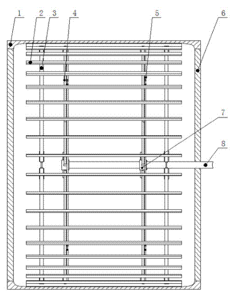
[0037] A high-efficiency energy-saving dryer with a spoiler structure, such as Figure 1~5 As shown, it includes a plurality of connecting rings 3 and a plurality of bar-shaped spoiler rods 2, and the plurality of connecting rings are coaxially arranged in the drying cylinder 1, and the outer edges of the multiple connecting rings are radially evenly distributed and fixed on the inner wall of the drying cylinder The innovation of the present invention is that each spoiler bar is solid and its outer surface is made into an arc that fits closely with the inner wall of the drying cylinder, and the outer surface of each spoiler bar is formed The curved surface of the machine makes the spoiler stick closely to the inner wall of the drying cylinder, and there will be no leakage of condensed water.

[0038] In this embodiment, each spoiler bar is made of high thermal conductivity metals such as aluminum and copper, and the bottom surface of the spoiler bar made of high thermal conduc...

Embodiment 2

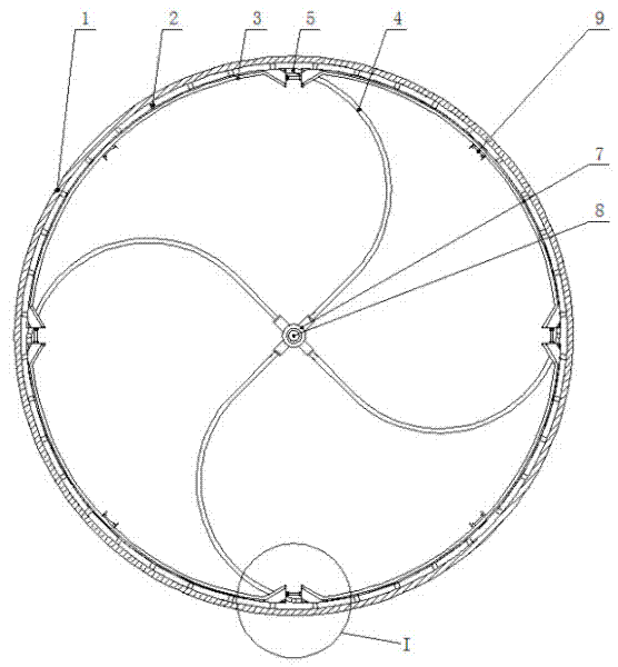
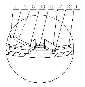
[0046] As shown in Examples 6 to 9 of this embodiment, the structure and size of multiple connecting rings and multiple spoiler rods, as well as the connection relationship between the two and the inner wall of the drying cylinder and the rotating shaft are the same as in Embodiment 1, except that the diameter is greater than 3 meters The structure of the annular water collection siphon device of the drying cylinder is: it includes two water collection rings, four arc-shaped connecting pipes, a five-way head and four connecting pipes. On the inside surface of the bar, each water collection ring is composed of four arc sections connected end to end through locking bolts 9 in turn, and a plurality of siphon ports 12 are evenly distributed on the outer surfaces of the four arc sections, and each siphon port is Spoiler sidewalls in opposite positions (see Figure 9 ), when the drying cylinder rotates, the condensed water accumulates on the side wall of the spoiler bar under t...


PUM


Abstract

The invention relates to a turbulent bar structure for a drying cylinder with the functions of high efficiency and energy saving, comprising a plurality of connection rings and bar-shaped turbulent bars, the plurality of connection rings are arranged in a drying cylinder coaxially, and the plurality of turbulent bars which are contacted with the internal wall of the drying cylinder are arranged fixedly and uniformly in radial direction on the peripheries of the plurality of connection rings. The structure is characterized in that each turbulent bar is solid and the external surface thereof isprovided with the cambered surface capable of attaching to the internal wall of the drying cylinder tightly. The turbulent bar structure of the invention has simple structure, scientific and reasonable number and size of the turbulent bar, and can effectively enhance the heat conductivity of the steam. Compared with the prior art, when the rotating speed is low, the surface temperature of the drying cylinder can be enhanced by 4 to 11 DEG C, and when the rotating speed is high, the surface temperature of the drying cylinder can be enhanced by 6 to 7 DEG C, thereby effectively ensuring the drying effect of the paper when the drying cylinder rotates in high speed, saving the energy on the whole, and enhancing the production efficiency.

Description

technical field [0001] The invention belongs to the field of papermaking and food drying equipment, in particular to a spoiler rod structure for a high-efficiency and energy-saving drying cylinder. Background technique [0002] The drying cylinder is an important drying equipment in the papermaking process. Its structure includes a cylindrical cylinder body and an end cover. An end cover is installed at the openings at both ends of the cylinder, and a hollow rotating shaft is coaxially embedded on the end cover on one side. The rotating shaft not only supports the rotation of the drying cylinder, but also installs a steam feed pipeline in its hollow interior. The drainage pipeline of condensate and condensate is equipped with a siphon device at the part where the rotating shaft extends into the drying cylinder. The siphon device is a bucket-shaped water-collecting siphon device, and its structure includes a bucket-shaped water collector. The installation structure can also ...

Claims


Application Information

Patent Timeline
Patent Type & Authority Patents(China)
IPC IPC(8): D21F5/02
Inventor 宋晓盖栋梁吕洪玉卞学询
Owner JIAOZUO CHONGYI LIGHT IND MACHINERY
Why Eureka
Try Eureka