Gob-side entry retaining reinforcing filling body structure and construction method thereof

A technology for filling bodies and entry retaining, which is applied in the direction of fillings, earthwork drilling, safety devices, etc. It can solve the problems of waste of wood and other raw materials, poor roofing effect, failure, etc., to achieve load-bearing characteristics, reduce erection, and structure simple effect

Inactive Publication Date: 2011-02-16
CHINA UNIV OF MINING & TECH
View PDF4 Cites 46 Cited by
  • Summary
  • Abstract
  • Description
  • Claims
  • Application Information

AI Technical Summary

Problems solved by technology

[0003] The shortcomings of using this method or the points that need to be improved are: 1. Due to the complex conditions of the roof of the underground working face, after the mining of the working face, the roof is uneven (or tilted or tilted), caving and net pockets are more common, and the open method is adopted. The top-connecting effect is poor when filling bags of the traditional type, and often only a small part of the filling body can be connected to the top, and it is necessary to wait for the filling body to solidify and place a wooden pile on its top to connect the top. On the one hand, raw materials such as wood are wasted; on the other hand, it makes Under the action of mine pressure, the roof of the roadway retaining slowly contacts the filling body, so that the peak value of t

Method used


Image

  • Gob-side entry retaining reinforcing filling body structure and construction method thereof
  • Gob-side entry retaining reinforcing filling body structure and construction method thereof
  • Gob-side entry retaining reinforcing filling body structure and construction method thereof

Examples


Embodiment Construction

[0019] An embodiment of the present invention will be further described below in conjunction with accompanying drawing:

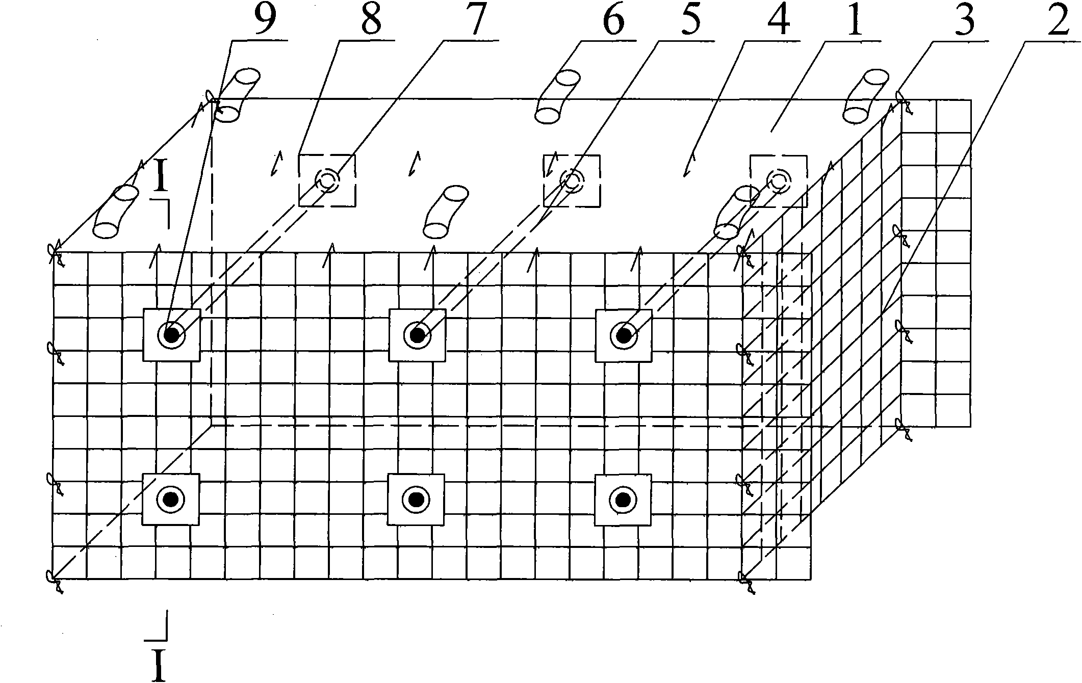
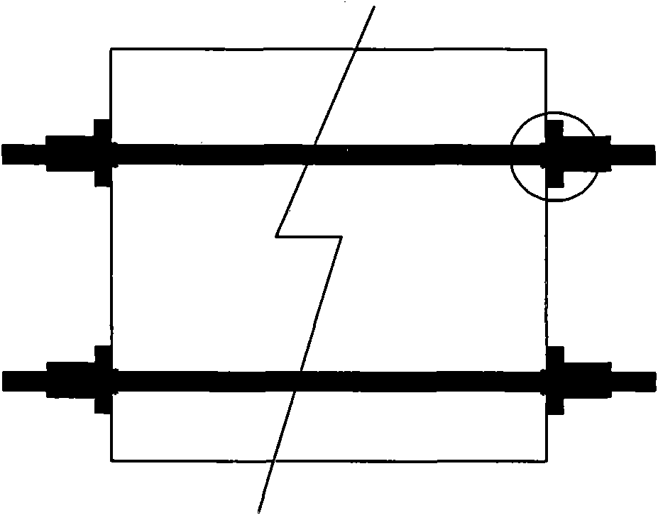
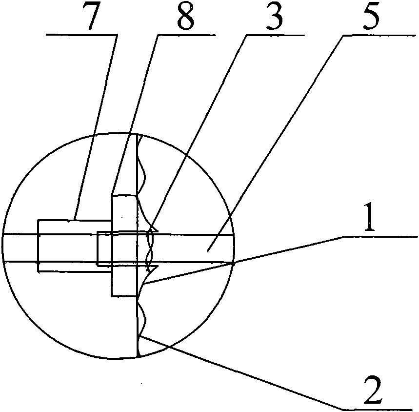
[0020] As shown in the accompanying drawings, the Gobside Entry Reinforced Filling Body Structure of the present invention includes a closed cuboid filling bag 1, and the top edge of the filling bag 1 is provided with several tops for filling and exhausting at intervals. The small bag 6 and the filling bag 1 are symmetrically arranged on both sides along the filling direction. There are several side small bags 9 that pass through the pull anchor rod 5. The pull anchor rod 5 passes through the side small bag 9, and its two ends are respectively equipped with trays. 8 and nut 7, the top and the periphery of the filling bag 1 are provided with some hooks 4 at intervals, and the surrounding of the filling bag 1 is provided with a mold-protecting steel mesh 2 fixed with iron wire 3.

[0021] The construction method of the gob-side entry retaining reinforcement f...


PUM


Abstract

The invention relates to a gob-side entry retaining reinforcing filling body structure and a construction method thereof. The method comprises the following steps of: making a filling bag into an enclosed oblong-shaped structure and sewing a plurality of small bags at the top edge of the filling bag and at the same position on two side faces along the filling direction, wherein the top small bag is used for filling feedstock and exhausting and a cross anchor is inserted into small bags on the side face for reinforcing a filling body and protecting sides; sewing hooks with certain densities inthe top central area of the filling bag and four side face lines which are certain distances away from the top of the filling bag, hanging the hooks on a top plate or four sides of a filling space, molding the filling body by using a reinforcement mesh and taking the reinforcement mesh as a reinforcing filling body for the cross anchor; before filling, inserting the cross anchor into the small bags on the side face, binding the small bags with a steel wire, putting a tray in place and screwing a screw cap; and during filling, plumping the filling bag until the filling bag is close to the roofby using the grout outlet pressure of a filling pump and enhancing anchor anchorage force to a preset value after the filling body reaches certain intensity so as to further realize the filling and reinforcing of the filling body. The structure is simple and is convenient to construct.

Description

technical field [0001] The invention relates to the technical field of underground mechanized construction of roadside filling bodies, in particular to a reinforcement filling body suitable for gob-side entry retention in deep high-stress mines and a construction method thereof. Background technique [0002] Gobside retention is to use a roadway twice, which greatly improves the resource recovery rate and relieves the tension of mining replacement. It is a major reform of coal mining and mining roadway layout technology. After entering deep mining, the mine pressure intensifies, the roadway diameter shrinks significantly, large deformation of gob-side retaining filling body occurs, and bearing failure increases, especially the unroofed filling body damage is more serious. Therefore, the filling and roof connection effect and filling body support are the key points in gob-side entry retention. The usual method of mechanized filling in the past is: 1. First, secure the single...

Claims


Application Information

Patent Timeline
IPC IPC(8): E21F15/00E21F15/02
Inventor 柏建彪陈勇夏军武王襄禹徐营慧功领
Owner CHINA UNIV OF MINING & TECH
Why Eureka
Try Eureka