
Gear pump

A gear pump, driven gear technology, applied in the direction of pressure lubrication of pumps, rotary piston pumps, lubricating pumps, etc., can solve the problems of gear pump oil pressure pulsation, etc., to reduce oil pressure pulsation, reduce fuel consumption, and improve power. Effect

Inactive Publication Date: 2011-02-16
CHERY AUTOMOBILE CO LTD
View PDF5 Cites 2 Cited by
  • Summary
  • Abstract
  • Description
  • Claims
  • Application Information

AI Technical Summary

Problems solved by technology

[0003] The purpose of the present invention is to provide a gear pump to solve the problem of excessive oil pressure pulsation in the current gear pump

Method used


Image

  • Gear pump
  • Gear pump
  • Gear pump

Examples


Embodiment 1

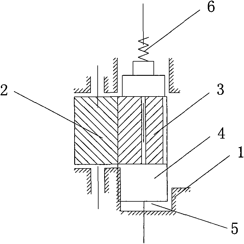
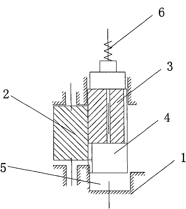
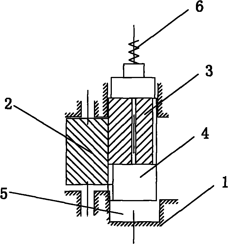
[0018] Example 1, such as figure 1 , 2 As shown, a gear pump includes a pair of meshing driving gear 2 and driven gear 3 in a housing 1; the housing 1 has an oil inlet and an oil outlet. One end of the driven gear 3 is also provided with a piston 4 and a control hydraulic cylinder 5 to promote its axial reciprocating movement, and the other end of the driven gear is also provided with a reset compression spring 6 for adjusting the pressure of the oil outlet. Described driving gear, driven gear are spur gears. The control oil pressure cylinder is connected and controlled by the pressure feedback signal from the main oil passage of the engine.

Embodiment 2

[0019] Embodiment 2, a gear pump, which includes a pair of meshing driving gears and driven gears in a housing; the housing has an oil inlet and an oil outlet. One end of the driven gear is also provided with a reciprocating electric actuator, which has a worm gear structure, and one end of the worm is connected to the driven gear.

Embodiment 4

[0020] Embodiment 4, a gear pump, which includes a pair of meshing driving gears and driven gears in a housing; the housing has an oil inlet and an oil outlet. One end of the driven gear is also provided with the reciprocating electric actuator, which has a screw structure, and one end of the screw is connected to the driven gear.


PUM


Abstract

The invention discloses a gear pump, comprising a pair of driving gear and driven gear which are engaged mutually in a shell, and an oil inlet and an oil outlet which are arranged on the shell. The gear pump is characterized in that one end of the driven gear is provided with a device which is used for driving the driven gear to perform axial reciprocating motion. The device comprises a control oil hydraulic cylinder on which a piston is arranged and the piston is driven to perform axial reciprocating motion, the top of the piston presses the driven gear, and the other end of the driven gear is also provided with a compression spring capable of regulating the pressure of the oil outlet and serving as resetting. The device can further be an electric actuator capable of performing the reciprocating motion. Due to the use of the device which is arranged on one end of the driven gear and can push the driven gear to perform in the axial reciprocating motion, the gear engagement length of the gear pump can be controlled, and the gear kneading length can be regulated automatically according to the pressure of the system. The gear pump can control the oil pressure after the filtration, with the accurate control and the oil pressure pulsation of the engine is reduced. The gear pump can meet the oil supplying requirement of the engine under the condition of ensuring the low speed performance of the engine particularly.

Description

technical field [0001] The invention relates to a gear pump, in particular to a variable displacement gear pump for an internal combustion engine which is beneficial to reducing the driving loss of the gear pump at high engine speed, reducing fuel consumption and controlling the system pressure accurately. Background technique [0002] The gear pump plays a decisive role in the entire engine lubrication system. It provides enough pressure and flow of oil for the entire engine to ensure that each friction part is fully lubricated and protects the relevant pressure-bearing parts. The current gear pump is a general rotor pump or gear pump. Under normal circumstances, the displacement of the gear pump is proportional to the engine speed. When the engine speed increases, the oil discharge of the gear pump increases proportionally. In fact, the oil supply required by each part of the engine does not need to be proportional to the engine speed. At low speed, the engine oil demand c...

Claims


Application Information

Patent Timeline
Patent Type & Authority Applications(China)
IPC IPC(8): F01M1/02F04C2/18F01M1/16
Inventor 倪伟付晓利羊富勇
Owner CHERY AUTOMOBILE CO LTD
Learn More