Two-channel coil antenna and device applying same

A coil antenna and dual-channel technology are applied in the field of dual-channel coil antennas and devices having the dual-channel coil antennas, and can solve the problems of sharp reduction in non-contact communication distance, serious mutual coupling, and increase in equipment volume.

Inactive Publication Date: 2011-02-16
BEIJING WATCH DATA SYST
View PDF5 Cites 15 Cited by
  • Summary
  • Abstract
  • Description
  • Claims
  • Application Information

AI Technical Summary

Problems solved by technology

[0004] In the process of realizing the above-mentioned dual-channel coil antenna, the inventors found that there are at least the following problems in the prior art: the mutual coupling between the two coils of the dual-channel coil antenna is very serious, which significantly reduces the performance of the coil antenna and makes the non-contact communication The distance decreases sharply. Although increasing the distance between the two coils properly can reduce the mutual coupling and help reduce the loss of the coil antenna Q (Quality factor, quality factor), but this will inevitably increase the size of the device, and the large In most cases, due to space constraints, it is difficult to increase the spacing between coil antennas

Method used


Image

  • Two-channel coil antenna and device applying same
  • Two-channel coil antenna and device applying same
  • Two-channel coil antenna and device applying same

Examples


specific Embodiment approach

[0059] The specific implementation is: the first conductor layer and / or the second conductor layer further includes: a terminal conductor section, the terminal conductor section is connected to the first or second conductor layer coil through the metalized through hole to form a three terminal Mode or one of the four-terminal mode; or

[0060] A section of the coil on the first and / or the second conductor layer is extended as a terminal conductor section to become a terminal of a three-terminal mode or a four-terminal mode.

[0061] The technical solutions in the embodiments of the present invention will be clearly and completely described below in conjunction with the accompanying drawings in the embodiments of the present invention. Obviously, the described embodiments are only a part of the embodiments of the present invention, rather than all the embodiments. Based on the embodiments of the present invention, all other embodiments obtained by those of ordinary skill in the art ...

Embodiment 1

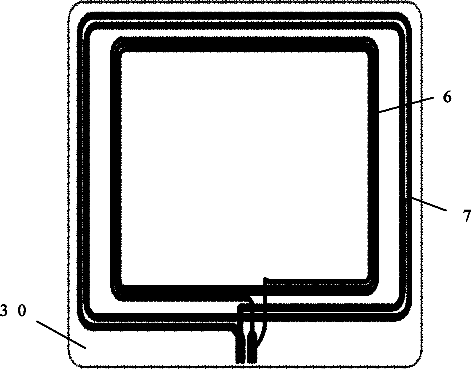
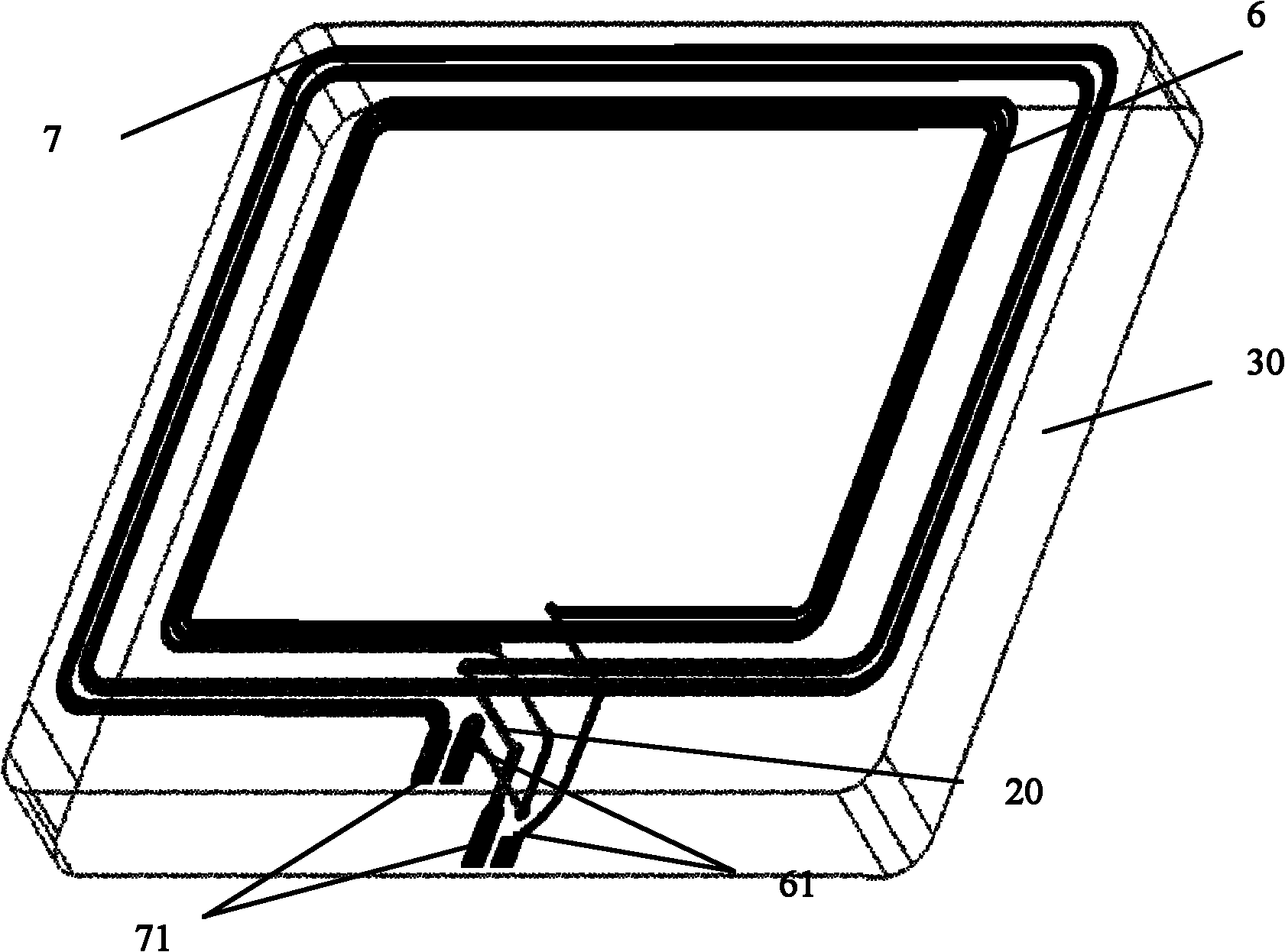
[0063] According to the number of input / output terminals in the antenna, this embodiment will specifically take a rectangular-diameter two-channel coil antenna with a three-terminal input / output mode as an example to provide a two-channel coil antenna 10, such as Figure 5 Shown, including:

[0064] A flexible or inflexible dielectric substrate 3, on the first surface and the second surface of the dielectric substrate 3 are respectively provided with a first conductor layer and a second conductor layer; the first conductor layer is composed of a spiral coil 5 , The second conductor layer is composed of spiral coils 4, wherein the projection of the first conductor layer coil on the plane where the second conductor layer coil is and the projection of the second conductor layer coil on the plane where Separated from each other. Because the first surface and the second surface of the dual-channel coil antenna 10 provided in this embodiment are parallel to each other (that is, the pla...

Embodiment 2

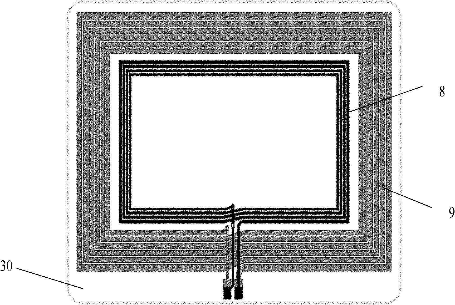
[0078] According to the number of input / output terminals in the antenna, this embodiment will specifically take a rectangular-diameter two-channel coil antenna with a four-terminal input / output mode as an example to provide a two-channel coil antenna 11, such as Figure 7 Shown, including:

[0079] A flexible or non-flexible dielectric substrate 31. The first and second surfaces of the dielectric substrate 31 are respectively provided with a first conductor layer and a second conductor layer; the first conductor layer is composed of a spiral coil 52, The second conductor layer is composed of spiral coils 42, wherein the projection of the first conductor layer coil on the plane of the second conductor layer coil and the projection of the second conductor layer coil on the plane of the second conductor layer are mutually Separate. Because the first surface and the second surface of the dual-channel coil antenna 10 provided in this embodiment are parallel to each other (that is, the...


PUM


Abstract

The embodiment of the invention discloses a two-channel coil antenna and a device applying the two-channel coil antenna, relating to the technical field of antenna and solving the technical problem that cross coupling of two coil antennae is strong in the two-channel coil antenna in the prior art. The two-channel coil antenna in the embodiment comprises a flexible or non flexible medium substrate, a first conductor layer and a second conductor layer are respectively correspondingly arranged on a first surface and a second surface of the medium substrate; the first conductor layer and the second conductor layer are all composed of coils, wherein projection of the coil of the first conductor layer along the normal direction of the plane where the first conductor layer is located and projection of the coil of the second conductor layer along the normal direction of the plane where the second conductor layer is located are mutually separate. The embodiment of the invention is mainly applied to scene of transmitting and receiving signals.

Description

Technical field [0001] The present invention relates to the field of antenna technology, in particular to a dual-channel coil antenna and a device with the dual-channel coil antenna. Background technique [0002] Readers of the RFID (Radio Frequency Identification) system generally use an antenna to emit electromagnetic waves to identify electronic tags. Some RFID systems use dual-channel coil antennas to send and receive signals according to application requirements, that is, one antenna completes the signal transmission, and the other antenna undertakes the signal reception. [0003] In the low frequency (125KHz) or high frequency (13.56MHz) RFID system, in order to ensure a certain communication distance, the reader antenna of the RFID system needs to generate a certain intensity of magnetic field. This type of antenna is usually implemented by an induction coil in the form of a printed circuit , This kind of coil can produce the required inductance in a tiny space. The usual ...

Claims


Application Information

Patent Timeline
Patent Type & Authority Applications(China)
IPC IPC(8): H01Q1/38H01Q7/00H01Q21/00
Inventor 刘建江
Owner BEIJING WATCH DATA SYST
Why Eureka
Try Eureka