Composite tensioning device

A tensioning device and sliding bearing technology, which is applied in the field of new composite tensioning devices, can solve the problems of hidden safety hazards, low efficiency, and high labor intensity, and achieve the effects of long component life, high efficiency, and low labor intensity

Inactive Publication Date: 2011-02-23
沈阳矿山机械有限公司
View PDF5 Cites 6 Cited by
  • Summary
  • Abstract
  • Description
  • Claims
  • Application Information

AI Technical Summary

Problems solved by technology

[0002] The tensioning device is installed on the tail frame of the heavy-duty apron feeder, and is used to tighten the chain to ensure the normal meshing of the chain and the sprocket in the chain plate device. , supporting wheel, tensioning shaft, expansion sleeve, screw, nut, composite spring, etc. When the tensioning force is more than ten tons, the labor intensity of the assembly workers during installation and debugging is particularly high, the efficiency is very low, and there is a safety hazard. Hidden danger

Method used


Image

  • Composite tensioning device
  • Composite tensioning device
  • Composite tensioning device

Examples


Embodiment Construction

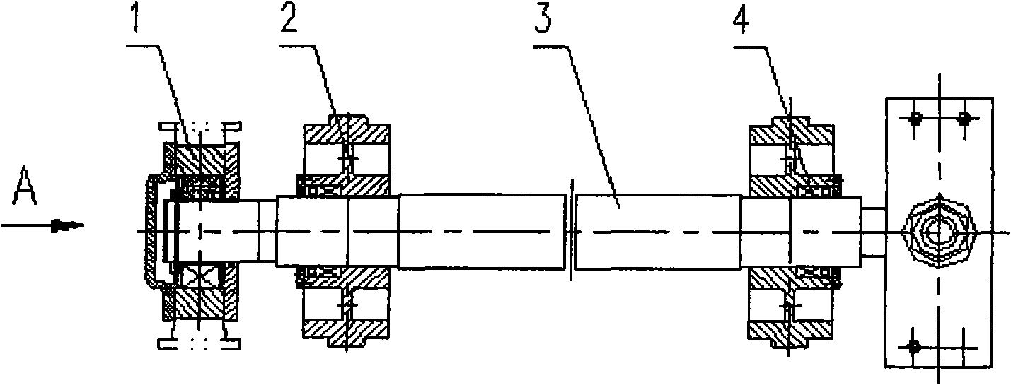
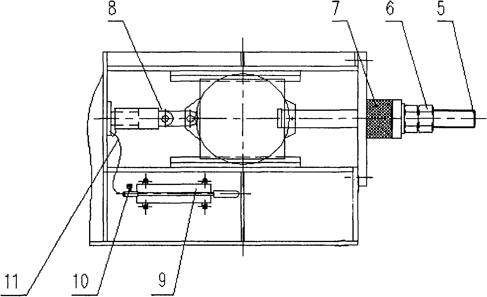
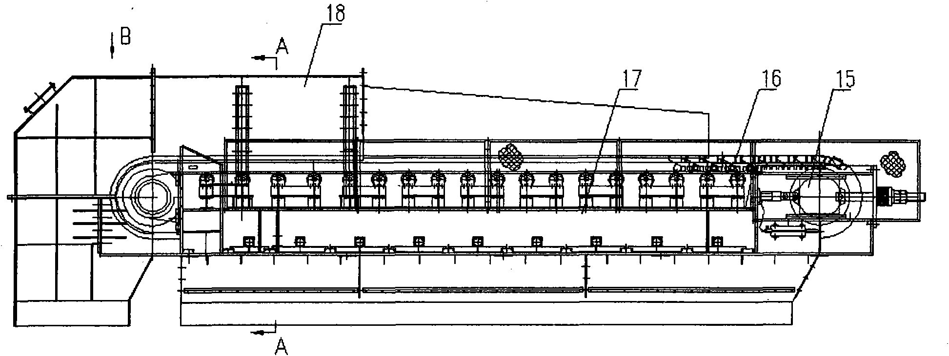
[0015] Referring to the accompanying drawings, a composite tensioning device, the whole device consists of a sliding bearing seat 1, a support wheel 2, a tensioning shaft 3, an expansion sleeve 4, a screw rod 5, a nut 6, a composite spring 7, an oil cylinder 8, a manual oil pump 9, Composed of a pressure gauge 10 and a pipeline 11, the sliding bearing seat 1, the supporting wheel 2, and the expansion sleeve 4 are installed on the tension shaft 3, and are installed on the tail frame, and the supporting wheel 2 supports the chain 24 on the chain plate device 16. , the front of the sliding bearing seat 1 is hinged with the oil cylinder 8, the base of the oil cylinder 8 is welded on the tail frame, the back of the sliding bearing seat 1 is connected with the screw rod 5, and the screw rod 5 passes through the tail frame through the composite spring 7, the nut 6 Tighten; the operation method of the composite tensioning device is to press the left and right sides of the handle of the...


PUM


Abstract

The invention discloses a composite tensioning device applied in the heavy plate feeder industry. The whole device consists of a sliding bearing seat, a supporting wheel, a tensioning shaft, an expansion sleeve, a lead screw, a nut, a composite spring, an oil cylinder, a manual oil pump, a pressure gauge and a pipeline, wherein the sliding bearing seat, the supporting wheel and the expansion sleeve are arranged on the tensioning shaft and arranged on a tail rack; the supporting wheel supports a chain on a link plate device; the front of the sliding bearing seat is hinged with the oil cylinder together, a base of the oil cylinder is welded on the tail rack, and the back of the sliding bearing seat is connected with the lead screw; and the lead screw passes through the tail rack and is screwed down through the composite spring and the nut. An operating method for the composite tensioning device comprises that: pressure oil passes through the pipeline, the pressure gauge and the oil cylinder by simultaneous left and right pressing of a handle of the manual oil pump to drive the tensioning shaft, the supporting wheel and the link plate device to move backwards together at the same time of pushing the sliding bearing seat to move backwards on the tail rack, and the nut on the lead screw is screwed down after the chain reaches a certain pre-tensioning force. The device has the advantages of low labor intensity, high strength, long service life of members and reasonable structure, ensures the reliable and safe operation of products, and meets the requirements of process and design aspects.

Description

Technical field: [0001] The invention relates to a composite tensioning device, in particular to a novel composite tensioning device for a heavy apron feeder. Background technique: [0002] The tensioning device is installed on the tail frame of the heavy-duty apron feeder, and is used to tighten the chain to ensure the normal meshing of the chain and the sprocket in the chain plate device. , supporting wheel, tensioning shaft, expansion sleeve, screw, nut, composite spring, etc. When the tensioning force is more than ten tons, the labor intensity of the assembly workers during installation and debugging is particularly high, the efficiency is very low, and there is a safety hazard. Hidden danger. Especially in the situation of being in line with international standards, more and more equipment is exported, and foreign companies put the labor intensity of workers in the first place. Therefore, researching and developing the composite tensioning device is a problem demandin...

Claims


Application Information

Patent Timeline
Patent Type & Authority Applications(China)
IPC IPC(8): B65G23/44
Inventor 原丽赵长海唐丽英王瑀许宝君杨敬洲张静波王伟星王伯旬贾晓峰刘兵杨斌商振宇
Owner 沈阳矿山机械有限公司
Why Eureka
Try Eureka