Drafting device capable of realizing mixed feeding of different raw materials on spinning frame

A drafting device and spinning frame technology, applied in the field of textile processing, can solve problems such as feasibility limitation and difficulty in spinning processing, and achieve the effect of easy operation

Inactive Publication Date: 2011-02-23
WUHAN TEXTILE UNIV +2
View PDF5 Cites 7 Cited by
  • Summary
  • Abstract
  • Description
  • Claims
  • Application Information

AI Technical Summary

Problems solved by technology

[0006] 2 Feasibility is limited
[0007] 3 Pre-spinning processing is difficult

Method used


Image

  • Drafting device capable of realizing mixed feeding of different raw materials on spinning frame
  • Drafting device capable of realizing mixed feeding of different raw materials on spinning frame
  • Drafting device capable of realizing mixed feeding of different raw materials on spinning frame

Examples


Embodiment 1

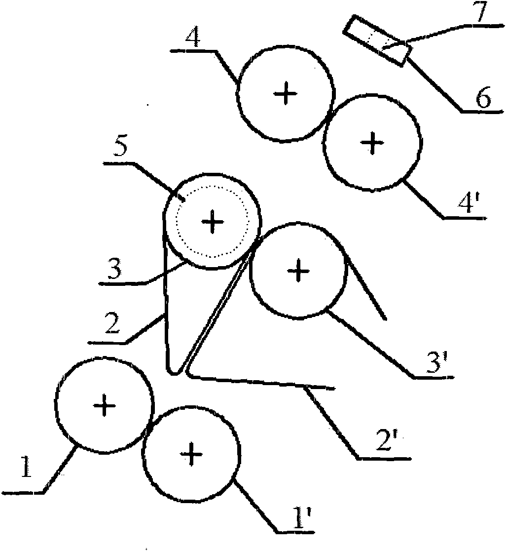
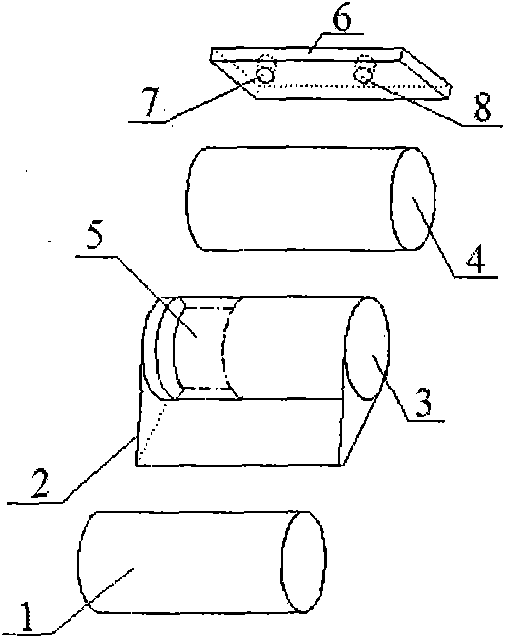
[0029] See figure 2 Open a positioning ring groove 5 with a width of 12 mm and a depth of 3 mm in the center of one side of the middle top roller 3 of the spinning frame, and a positioning yarn feeding hole 7 with a diameter of 5 mm and a diameter of 5 mm on the positioning yarn feeding device 6. The yarn feeding hole 8 of 5mm locates the yarn feeding hole 7 and the yarn feeding hole 8 on the same horizontal line. The axis of the positioning yarn feeding hole 7 is collinear with the center line of the positioning annular groove 5, and the yarn feeding hole 8 is positioned at the side of the positioning yarn feeding hole 7. Set the center distance between front roller 1' and rear roller 4' as 140mm, and set the center distance between front roller 1' and middle roller 3' as 45mm. The above-mentioned structure is suitable for drafting of wool fiber and cotton fiber blended yarn.

[0030] Two wool staple fiber rovings and cotton staple fiber rovings (wherein the main body leng...

Embodiment 2

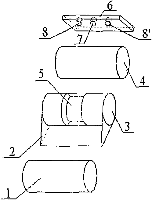
[0032] See image 3 Open a positioning annular groove 5 with a width of 10 mm and a depth of 3.5 mm in the middle of the middle top roller 3 of the spinning frame, and a positioning yarn feeding hole 7, a yarn feeding hole 8 and a yarn feeding hole on the positioning yarn feeding device 6 8', positioning the yarn feeding hole 7, the yarn feeding hole 8 and the yarn feeding hole 8' on the same horizontal line, and their apertures are 5mm. The axis of the positioning yarn feeding hole 7 is collinear with the center line of the positioning annular groove 5, and the yarn feeding hole 8 and the yarn feeding hole 8 ' are positioned at both sides of the positioning yarn feeding hole 7 respectively. Set the center distance between front roller 1' and rear roller 4' to be 145mm, and set the center distance between front roller 1' and middle roller 3' to be 50mm. The above structure is suitable for drafting of cashmere, viscose and polyester staple fiber blended yarns.

[0033] A bar ...

Embodiment 3

[0035] See Figure 4 In the middle of both sides of the middle top roller 3 of the spinning frame, a positioning annular groove 5 and a positioning annular groove 5' with a width of 8mm and a depth of 4mm are opened respectively, and two positioning yarn feeding holes 7 are opened on the positioning yarn feeding device 6. With 7 ' and a yarn feeding hole 8, positioning yarn feeding hole 7 and 7 ' and yarn feeding hole 8 are on the same horizontal line, and their apertures are 5mm. The axis of positioning yarn feeding hole 7 and positioning yarn feeding hole 7' is collinear with the midline of positioning annular groove 5 and 5' respectively, and yarn feeding hole 8 is positioned in the middle of positioning yarn feeding hole 7 and positioning yarn feeding hole 7'. Set the center distance between front roller 1' and rear roller 4' as 143mm, and set the center distance between front roller 1' and middle roller 3' as 42mm. The above-mentioned structure is suitable for drafting o...


PUM

PropertyMeasurementUnit
lengthaaaaaaaaaa
lengthaaaaaaaaaa
lengthaaaaaaaaaa

Abstract

The invention relates to a drafting device capable of realizing mixed feeding of different raw materials on a spinning frame, and belongs to the technical field of textile processing. The invention adopts the technical scheme that: the surface of a middle leather roller of a drafting mechanism is provided with positioned annular single grooves or positioned annular double grooves at different positions along the circumferential direction, an upper leather ring is sleeved on the surface of the middle leather roller, a lower leather ring is sleeved on the surface of a middle roller, a positioned yarn feeding device is arranged in back of the drafting mechanism of the spinning frame, the positioned yarn feeding device is provided with positioned yarn feeding holes corresponding to the positioned annular grooves on the middle leather roller, the positioned yarn feeding device is also provided with one or more yarn feeding holes, and the positioned yarn feeding holes and the yarn feeding holes are on the same horizontal line. The drafting mechanism of the spinning frame provided by the invention can change the feeding and drafting forms of the conventional spinning frame and adapt to simultaneous feeding and drafting of a plurality of rove strands consisting of single-component fibers of different categories.

Description

technical field [0001] The invention relates to a drafting device for realizing mixed feeding of different raw materials on a spinning frame, belonging to the technical field of textile processing. Background technique [0002] In recent years, clothing made of multi-component textile materials has become very popular in the market. Multi-component textile raw materials can make use of the respective advantages of different textile fibers (such as wool has excellent warmth retention and elasticity, and silk has elegant luster) to produce clothing that is completely different in appearance or function from a single textile raw material fabric. Expand the scope of use of textile raw materials. [0003] At present, the existing ring spinning frame can't complete the task of spinning multi-component textile raw material yarn well. This is mainly because the drafting mechanism of the ring spinning machine is designed for the spinning of certain fiber inherent physical indicator...

Claims


Application Information

Patent Timeline
Patent Type & Authority Applications(China)
IPC IPC(8): D01H5/26D01H13/04D01H5/78D01H5/76
Inventor 徐卫林田野沈小林杨进陈军华永诚甄雅璋
Owner WUHAN TEXTILE UNIV
Why Eureka
Try Eureka