Wave energy generating set

A power generation device and wave energy technology, which is applied in the field of wave energy power generation devices, can solve the problems of not being able to realize large-scale, industrial application, safety and reliability and wave energy conversion rate, and energy consumption of automatic control systems. , to achieve the effects of improving wave energy conversion efficiency, reducing power generation costs, and low construction costs

Active Publication Date: 2011-03-09
青岛海经海洋能源工程技术股份有限公司
View PDF7 Cites 25 Cited by
  • Summary
  • Abstract
  • Description
  • Claims
  • Application Information

AI Technical Summary

Problems solved by technology

[0002] At present, there are mainly the following problems in the use of wave energy generation devices: the safety and reliability and the wave energy conversion rate cannot be balanced, the construction cost is high, and the terrain or sea conditions are restricted, and the scale cannot be well realized. application
Its disadvantages are: the wave energy generating device is equipped with an automatic control system, which makes the device too complicated, has poor reliab

Method used


Image

  • Wave energy generating set
  • Wave energy generating set
  • Wave energy generating set

Examples


Embodiment 1

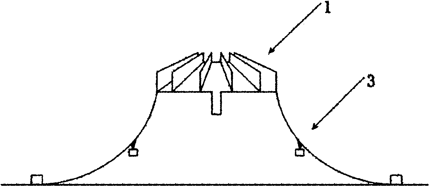
[0042] see figure 1 and image 3 , The wave energy generating device includes a wave energy collection and conversion system 1 , a hydroelectric power generation system 2 and an anchoring system 3 .

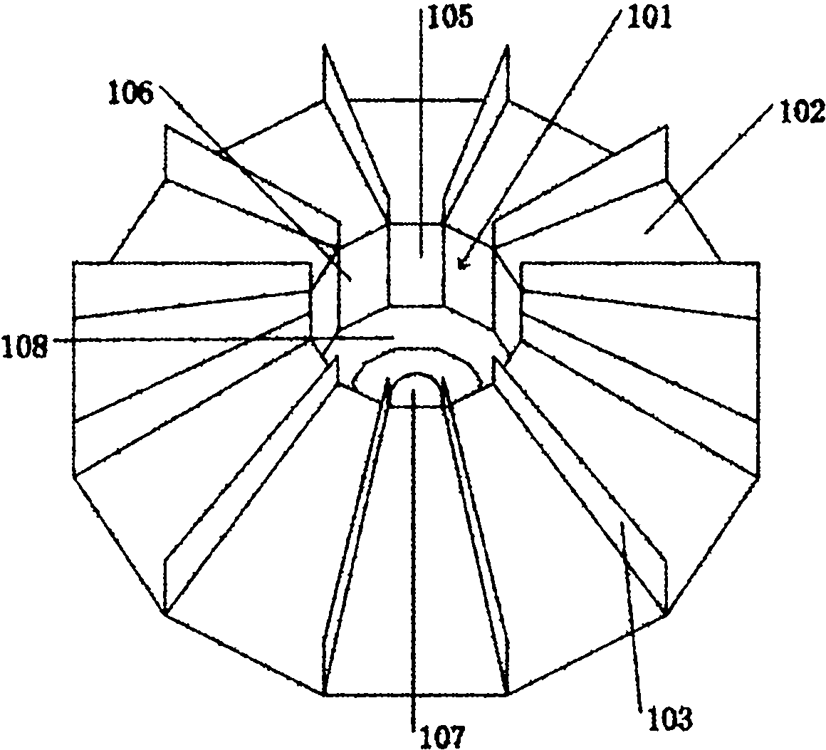
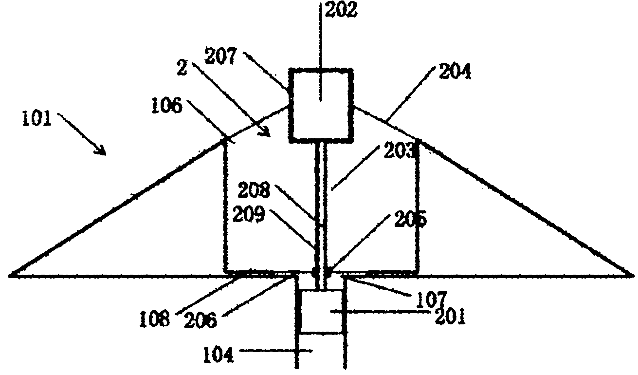
[0043] see Figure 2-Figure 5 , The wave energy collection and conversion system 1 includes a water storage tank 101 , a wave guiding plate 102 , a wave gathering plate 103 and a water outlet pipe 104 . The reservoir 101 is a hollow equilateral twelve prism structure surrounded by 12 side plates 105, its cross section is an equilateral twelve prism, the upper part is a water inlet 106, and the bottom is provided with a water outlet 107 and a bottom platform 108 . A wave-guiding plate 102 is arranged outside the reservoir, the upper end of the wave-guiding plate 102 is connected to the upper end of the side plate 105 of the reservoir, and the lower end extends obliquely to the bottom plane of the reservoir. The wave-guiding plate 102 has a slope of 2:3, which is suitable for w...

Embodiment 2

[0053] see Figure 9-Figure 15 , The water turbine 201 is a curved blade water turbine 220, which is fixed in the water outlet pipe 104 through a bearing 226. The upper end of the outlet pipe 104 is provided with an S-shaped deflector 225 , one end of the deflector 225 is fixed on the wall of the outlet pipe, and the other end extends to the upper end of the blade 223 of the curved blade turbine 220 . When the curved blade type water turbine 220 is selected, the transmission mechanism 203 includes two transmission shafts 208 and two steering bearings 224, one end of the two transmission shafts 208 is respectively connected to the generator 202, and the other end is connected to the curved blade type water turbine through the steering bearing 224. One end of the rotating shaft 222 of 220 is connected. The curved blade type water turbine 220 includes a rotating shaft 222 and blades 223. The rotating shaft 222 is provided with a casing 221. The blades 223 are installed on the ca...


PUM

PropertyMeasurementUnit
Chord lengthaaaaaaaaaa
Leaf widthaaaaaaaaaa

Abstract

The invention relates to a wave energy generating set which has the advantages of high efficiency and high reliability. The invention aims to provide a wave energy generating set which has the advantages of high efficiency, high reliability and low construction cost. The invention has the technical scheme that the wave energy generating set comprises a wave energy collection and conversion system, a water wheel generating system and an anchorage system, wherein the wave energy collection and conversion system comprises a reservoir, a wave guide plate, a wave collection plate and a water outlet pipe; the water wheel generating system comprises a water turbine, a generator and a transmission mechanism, the water turbine and the generator are arranged at up and down through the transmission mechanism, and the water turbine is positioned below the generator; and the anchorage system comprises an anchor chain, a loading hanging block and a gravity anchor, the gravity anchor is anchored on the seabed, one end of the anchor chain is fixed on the gravity anchor, the other end is connected to the corner end on the bottom of the outer side of the reservoir, the anchor chain is symmetrically distributed by using the reservoir as the center, and the loading hanging block is hung on the anchor chain through a short chain. The invention has the advantages of high wave energy utilization ratio, high wave energy conversion rate, favorable overall stability and high reliability.

Description

technical field [0001] The invention relates to a power generation device using wave energy, in particular to a wave power generation device with high efficiency and high reliability. Background technique [0002] At present, there are mainly the following problems in the use of wave energy generation devices: the safety and reliability and the wave energy conversion rate cannot be balanced, the construction cost is high, and the terrain or sea conditions are restricted, and the scale cannot be well realized. application. [0003] The patent application with the application number 200910050526.X discloses a floating cofferdam type wave energy generating device, which utilizes the potential energy and kinetic energy of waves during tidal fluctuations and converts them into electrical energy through a hydroelectric generator. The disadvantage is that the wave energy generating device is equipped with an automatic control system, which makes the device too complicated, has poo...

Claims


Application Information

Patent Timeline
IPC IPC(8): F03B13/22F03B3/12B63B21/04
CPCY02E10/223Y02E10/38Y02E10/20Y02E10/30
Inventor 史宏达刘臻刘娅君邵萌黄燕刘栋王鸿旭
Owner 青岛海经海洋能源工程技术股份有限公司
Why Eureka
Try Eureka