Pipeline hydraulic test device

A hydraulic test and pipeline technology, applied in the direction of applying stable tension/pressure to test the strength of materials, using liquid/vacuum to measure liquid tightness, etc., can solve problems such as high cost, high cost of production line equipment, and large capital investment , to achieve the effect of good effect and less investment

Active Publication Date: 2011-03-09
NANJING BAOSE
View PDF5 Cites 15 Cited by
  • Summary
  • Abstract
  • Description
  • Claims
  • Application Information

AI Technical Summary

Problems solved by technology

However, it is often necessary to invest a lot of cost in the corresponding process improvement of the pipeline, and the purchase of the corresponding radial sealing pressure test device also requires a large capital investment, and the cost of production line equipment is very high

Method used


Image

  • Pipeline hydraulic test device
  • Pipeline hydraulic test device
  • Pipeline hydraulic test device

Examples


Embodiment Construction

[0029] In order to make the content of the present invention more obvious and understandable, the present invention will be further described in conjunction with the accompanying drawings and specific embodiments.

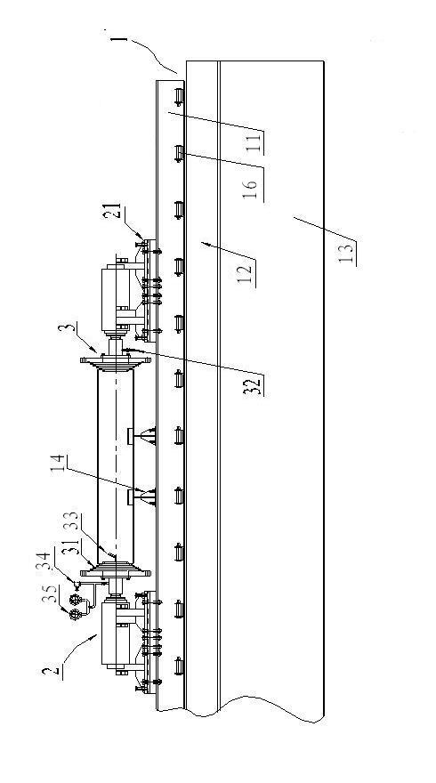
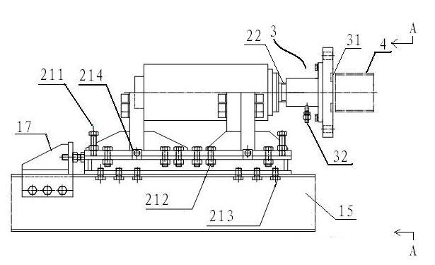
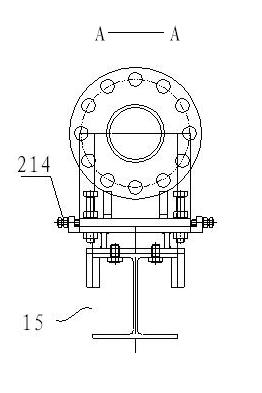
[0030] combine Figure 1 to Figure 7 As shown, the pipeline hydraulic testing device of the present invention includes a testing machine body 1, and the bed 1 is provided with a hydraulic thrust power unit, a pipeline connector 3, a composite seal 31, and a bracket 14, wherein: the universally adjustable base 21 It is detachably installed on the bed 1, which includes a U-shaped top plate, a vertical adjustment mechanism 211, and a horizontal adjustment structure 214. The bottom plate of the hydraulic thrust power unit is located in the groove of the U-shaped top plate; the vertical adjustment mechanism 211 is installed vertically on the On the four corners of the bottom plate of the hydraulic thrust power unit, and between the bottom plate of the hydraulic thrust p...


PUM


Abstract

The invention provides a pipeline hydraulic test device, which consists of beds, hydraulic thrust power units, pipeline connecting pieces, composite sealing elements and supports. Two hydraulic power units are removably fixed to beds by universal adjusting bases based on the lengths of the pipelines to be tested. Seal flange is used as the conduit coupling. One end of the conduit coupling is connected to the thrust bar of hydraulic thrust power units. Composite sealing elements are arranged at the connection place of the sealing surface of the other end of the conduit coupling and tube walls. The composite sealing elements are compounded of high toughness rubber bases and flexible metal anti-shear layers. Being connected with the pipelines to be tested, flexible metal anti-shear layers can resist the edge cutting of pipelines against the sealing elements, and high toughness rubber bases make up the deviation between sections generated from tack cutting of pipelines and axial verticality of pipelines. The axial sealing is realized without considering on the high requirements of inner and outer diameter surface smoothness or other parameters of the pipelines to be tested by adopting other sealing types. The device provided by the invention acts more effectively with less input.

Description

technical field [0001] The invention relates to the technical field of high and medium pressure hydraulic detection for finished large and medium diameter welded pipes and pipe fittings, in particular to a pipeline hydraulic test device. Background technique [0002] In the process of professional welded pipeline manufacturing, it is a very important step to perform hydrostatic test on the pipeline according to the relevant technical requirements to check its mechanical properties and pipeline connection quality. At present, the sealing form of welded (middle longitudinal seam, spiral seam) pipeline (steel oil and natural gas pipeline) hydraulic pressure test is generally radial seal at both ends of the length direction of the unit pipe section, that is, the inner diameter or outer diameter of the welded pipe is adopted. Cooperate with the sealing ring, through the pressure expansion of the sealing ring to achieve the purpose of sealing the pipe wall. This is the form of th...

Claims


Application Information

Patent Timeline
Patent Type & Authority Applications(China)
IPC IPC(8): G01N3/12G01M3/02
Inventor 乔迎才王承益汪君楠
Owner NANJING BAOSE
Why Eureka
Try Eureka