Punch safety device as well as punch and refitting method thereof

A safety device, punching technology, applied in safety equipment, metal processing equipment, manufacturing tools, etc., can solve problems such as damage accidents and downward movement of sliders, and achieve the effects of reliable safety performance, improved safety, and low implementation costs.

Active Publication Date: 2011-03-16
NINGBO MINTH AUTOMOTIVE PARTS RES&DEV CO LTD
View PDF6 Cites 16 Cited by
  • Summary
  • Abstract
  • Description
  • Claims
  • Application Information

AI Technical Summary

Problems solved by technology

However, in the prior art, once the light curtain senses a foreign object, there are still deficiencies in the braking execution process: once the punch press operator or others make a wrong action, it will happen when the punch press flywheel has driven the crankshaft slider to move downward from the top dead center. At this time, although the light curtain sensor senses it and sends out a signal, the motor stops, but at this time the slider will move downward under the action of inertia and self-gravity, resulting in damage accidents

Method used


Image

  • Punch safety device as well as punch and refitting method thereof
  • Punch safety device as well as punch and refitting method thereof
  • Punch safety device as well as punch and refitting method thereof

Examples


Embodiment 1

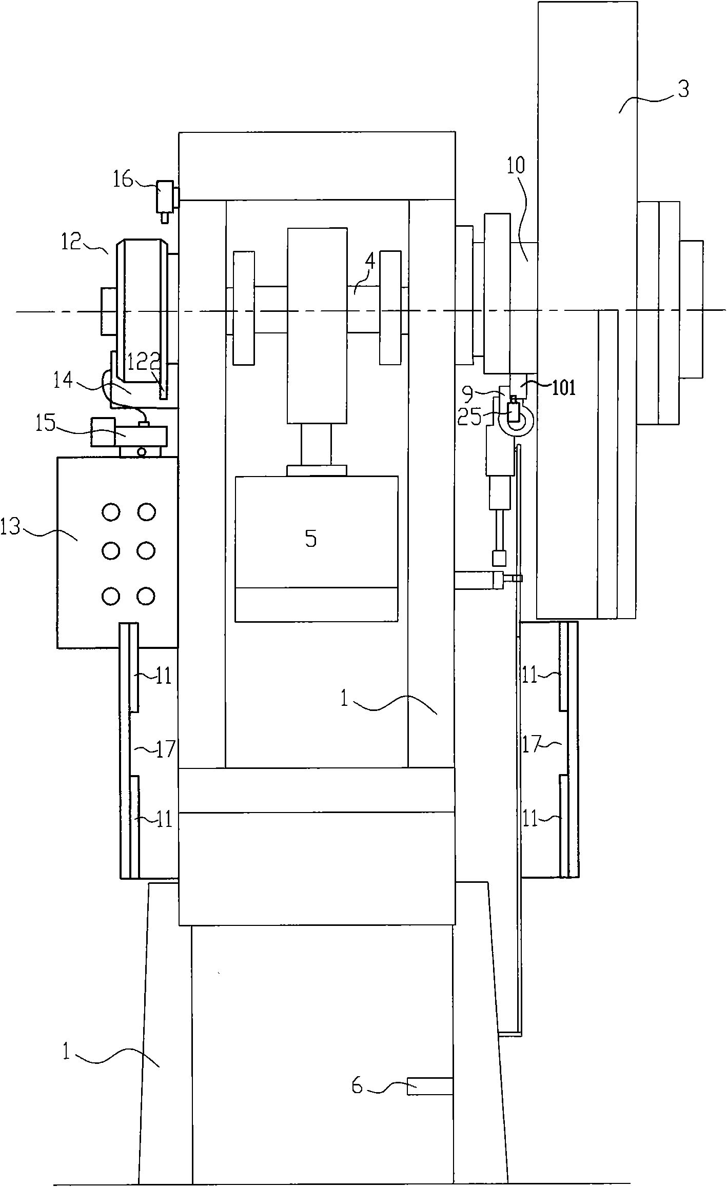
[0030] like Figure 1 to Figure 4 Shown, J23 series open tilting punch press, see as figure 1 , figure 2 The thin line part is shown. Including the frame 1, the motor 2 set on the rear upper part of the frame 1 drives the flywheel 3 through the belt, and the flywheel 3 is equipped with a clutch, which is vacantly sleeved on the crankshaft 4, and the clutch function is realized through the clutch of the movable key; J23 series open type The tiltable punching machine ensures that the clutch is in the disengaged state in the normal state through the following scheme: a runner 10 with a block 101 is placed on the crankshaft 4 close to the flywheel 3 and forms a linkage relationship with the clutch. When the runner 10 is blocked by another object, it will not When the clutch is in motion, the clutch cannot rotate and it is in a disengaged state; when the clutch is in a disengaged state, the flywheel 3 is in an idling state; once the other object is not blocked, the runner 10 wil...

Embodiment 2

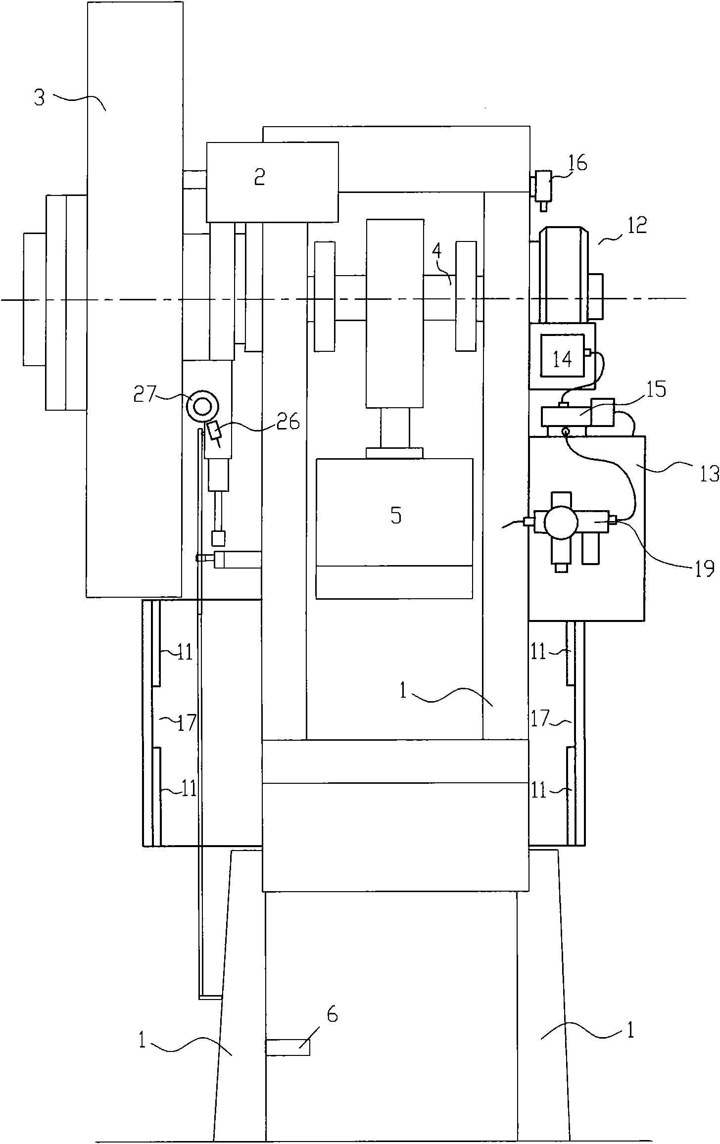
[0038] This embodiment is a further improvement on the basis of Embodiment 1. The button control method is used to replace the traditional pedal-operated start control method, that is, the button-operated mechanism is used to replace the pedal-operated mechanism to further improve the punching pressure. Process safety, while improving the ease of operation and automation of the punch press.

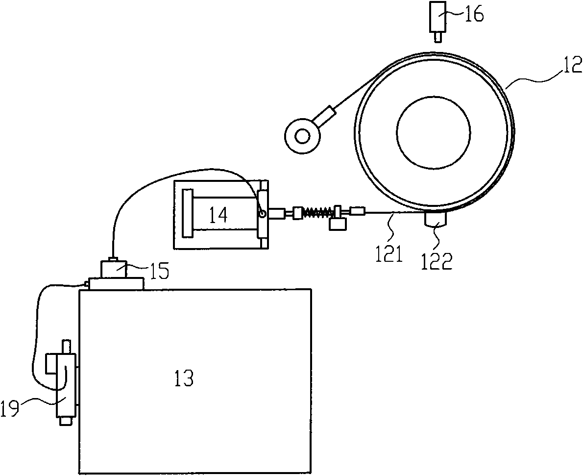
[0039] like Figure 5 to Figure 7 As shown, the thin line part also represents the domestic common J23 series open tilting punch presses (called presses) used by the safety device of the present invention. The safety device of the present invention can be found in Figure 1 to Figure 4 As shown in the thick line, it includes infrared light curtains 11 arranged on both sides of the front of the press console, a friction wheel brake device 12 arranged at the other coaxial end of the flywheel of the punch, and a matching device arranged at a suitable position around the punch or its surround...


PUM


Abstract

The invention relates to a crank shaft slide block type punch safety device which can immediately brake at any time in operation once the danger occurs. The punch safety device comprises infrared light curtains, a friction wheel braking device, a distribution control box and a first cylinder, wherein the infrared light curtains are arranged at two sides of the front of a punch operating table; the friction wheel braking device is arranged at the other end of the same shaft of a punch flywheel; the distribution control box is arranged on the punch or at the proper position around the punch; the first cylinder is arranged beside the friction wheel braking device, is used for driving the friction wheel braking device and is connected with a first electromagnetic control air valve through an air pipe; the air valve is provided with a compressed air input port; and the infrared light curtains and an electrical control pneumatic valve are electrically connected with the distribution control box. The punch safety device can also comprise a first travel switch which is arranged beside a friction wheel and is used for monitoring the return stroke of the punch head of the punch, and correspondingly, a convex block which is suitable for being sensed by the first travel switch is arranged on the circumference of the friction wheel of the friction wheel braking device.

Description

technical field [0001] The invention relates to a punch press safety device, a punch press and a refitting method thereof, in particular to a crank slider type punch press safety device driven by a flywheel, a punch press and a refitting method thereof. Background technique [0002] How to get rid of the frequent personal injury accidents such as finger injury and severed finger caused by the operator due to operating errors has always plagued the stamping processing industry. In response to this problem, people in the industry have been seeking effective solutions. In the existing technology that has been formed for a long time, there are many kinds of safety protection devices specially used for punching machines. There are mainly two types. One is a mechanical safety protection device, which has poor adjustability of the mechanism and greatly interferes with the punching operation. The other type is the photoelectric induction safety protection device commonly used at pr...

Claims


Application Information

Patent Timeline
Patent Type & Authority Applications(China)
IPC IPC(8): B21D55/00B21D22/02
Inventor 乐拥军陈剑东张孝峰
Owner NINGBO MINTH AUTOMOTIVE PARTS RES&DEV CO LTD
Why Eureka
Try Eureka