Full circular motion limiting method and equipment

A full-circle, motion technology, applied in the direction of feedback control, etc., can solve the problems of occupying space and cannot meet the requirements of full-circle motion, and achieve reliable performance, low cost, and simple processing logic.

Active Publication Date: 2011-03-16
NANJING NAIERSI PHOTOELECTRIC INSTR
View PDF3 Cites 11 Cited by
  • Summary
  • Abstract
  • Description
  • Claims
  • Application Information

AI Technical Summary

Problems solved by technology

At this time, if the limit switch is still simply installed, because the front and back limit switches need to occupy space, that is, occupy a part of the angle, it will inevitably cause the rotation range to be less than 360 degrees, which cannot meet the requirements of full circular motion.

Method used


Image

  • Full circular motion limiting method and equipment
  • Full circular motion limiting method and equipment
  • Full circular motion limiting method and equipment

Examples


Embodiment 1

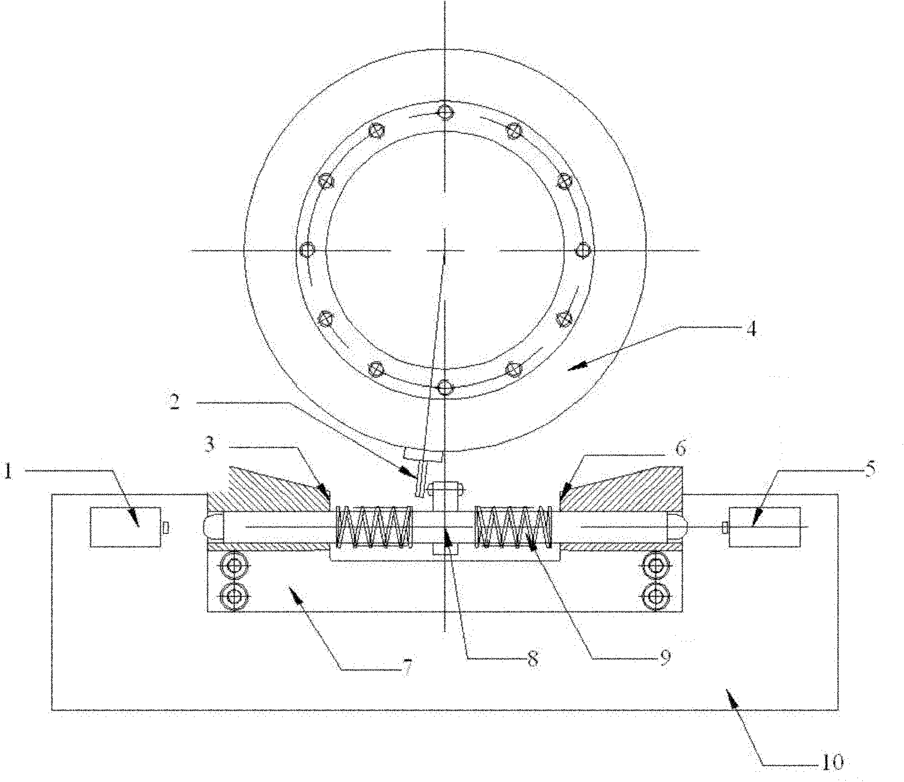
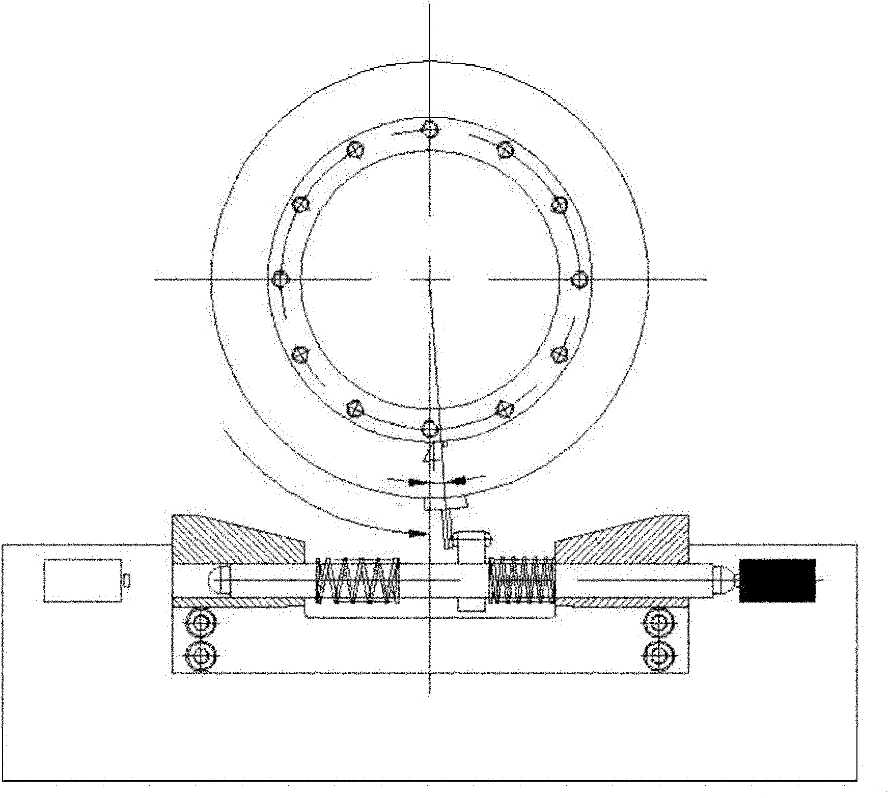
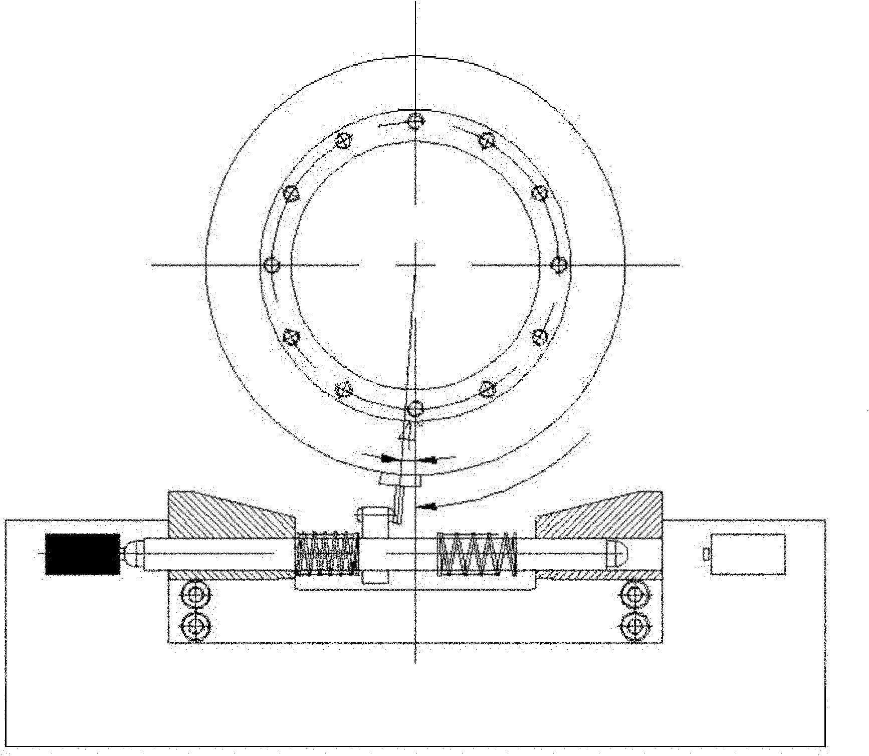
[0019] Embodiment 1: The limit of the movement of the azimuth axis of the "two-dimensional antenna test turntable", the rotation range is 360 degrees, so as to ensure that the antenna signal pattern of the full circumference is given. At an appropriate position outside the rotating part of the azimuth axis, a "rotation feeler rod" is installed, which rotates with the rotation of the azimuth axis; see figure 1 :

[0020] On the fixed part (fixed base plate 10, fixed seat 7) of azimuth shaft (rotating shaft) 4, a set of position limiting device is installed, and profile is a cuboid, and its two ends are touch switch 1,5 (as travel switch, contact switch, Photoelectric switch, etc.), used to generate limit signals, the center along the long axis is a slidable "sliding rod" 8, a "stopper" protrudes from the center of the "sliding rod" 8, and the two sides of the "sliding rod" Each cover a compression spring 9.

[0021]

[0022] The processing flow is as follows:

[0023] ⑴.. W...


PUM


Abstract

The invention discloses a full circular motion limiting method and full circular motion limiting equipment. A rotating feeler lever is fixed on the outer side of a rotating body; on an immobilized body, a sliding bar is arranged in parallel to the tangent line of the external circle of the rotating body, and springs are sleeved on two sides of the sliding bar; a stop block is vertically arranged on the sliding bar, the top of the stop block is positioned between the external circle of the rotating body and the rotating track of the rotating feeler lever, and two ends of the sliding bar are provided with trigger switches for generating limit signals; a shaft rotates to drive the rotating feeler lever to rotate; when the shaft rotates clockwise to reach a limit position soon, the rotating feeler lever touches the stop block; the shaft continuously rotates to pull the sliding bar to move to one side, the compressed springs touch the contact switches to generate clockwise limit signals; when the shaft is released from clockwise limit, the sliding bar is rebounded to the center, and the clockwise limit signals disappear; and the anticlockwise rotating process is opposite. The method and the device have the advantages of implementation of limit of full circular motion, no time sequence relationship due to direct corresponding between the limit signals and the limit directions, reliable performance, simple processing logic and low cost.

Description

technical field [0001] The invention belongs to the field of electromechanical integration instruments and equipment, and in particular relates to a method and equipment for position limitation of full circular motion (360 degrees). Background technique [0002] Many electromechanical systems are composed of multiple rotating shafts (such as turntables), and each rotating shaft can rotate at a certain angle. In order to prevent the rotation from exceeding the allowable range, detection elements (such as travel switches, contact switches, , photoelectric switch, etc.), when turning to both sides of the range, the detection element is triggered to generate an electrical signal (called a limit signal). After the electric control system detects the limit signal, it stops the rotation in the original direction, but still It can move in the opposite direction of this direction, so that it can ensure that the rotation will not exceed the limited range and ensure the safety ...

Claims


Application Information

Patent Timeline
Patent Type & Authority Applications(China)
IPC IPC(8): G05D3/12
Inventor 李道友朱庆生郑锋华
Owner NANJING NAIERSI PHOTOELECTRIC INSTR
Why Eureka
Try Eureka