Scattering correction method of CT system and CT system

A scatter correction and corrected technology, applied in the field of simulation imaging, can solve problems such as low efficiency

Active Publication Date: 2011-03-23
SHENZHEN INST OF ADVANCED TECH CHINESE ACAD OF SCI
View PDF4 Cites 31 Cited by
  • Summary
  • Abstract
  • Description
  • Claims
  • Application Information

AI Technical Summary

Problems solved by technology

In addition, for the same scanned object, it needs to be scanned twice, the scanning time is doubled, and the amount of data processed is also doubled, which is very inefficient.

Method used


Image

  • Scattering correction method of CT system and CT system
  • Scattering correction method of CT system and CT system
  • Scattering correction method of CT system and CT system

Examples


Embodiment Construction

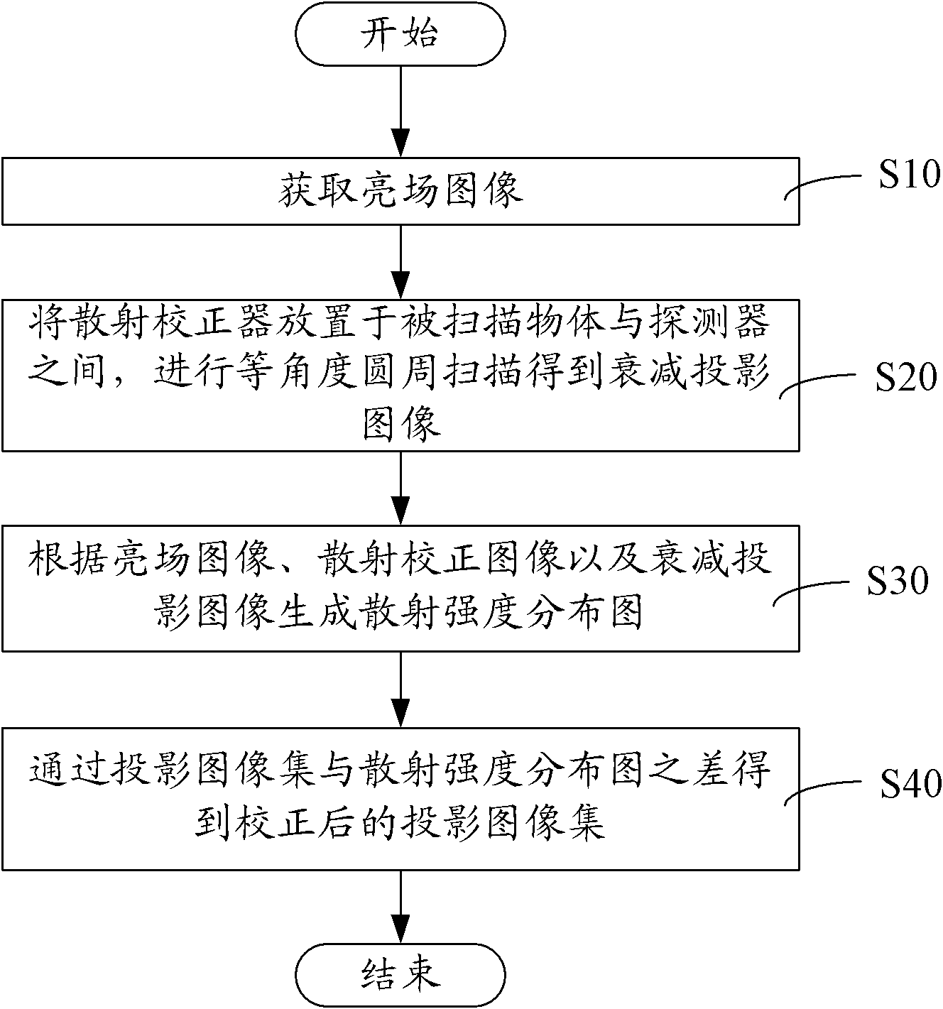
[0029] figure 1 A scatter correction method for a CT system in an embodiment is shown, including the following steps:

[0030] In step S10, a bright field image is acquired. In this embodiment, no object is placed in the scanning field of view, and the bright field image is obtained by scanning the bright field. The scanned object is not placed in the imaging field of view, and the scanned image obtained by turning on the light source is the current image.

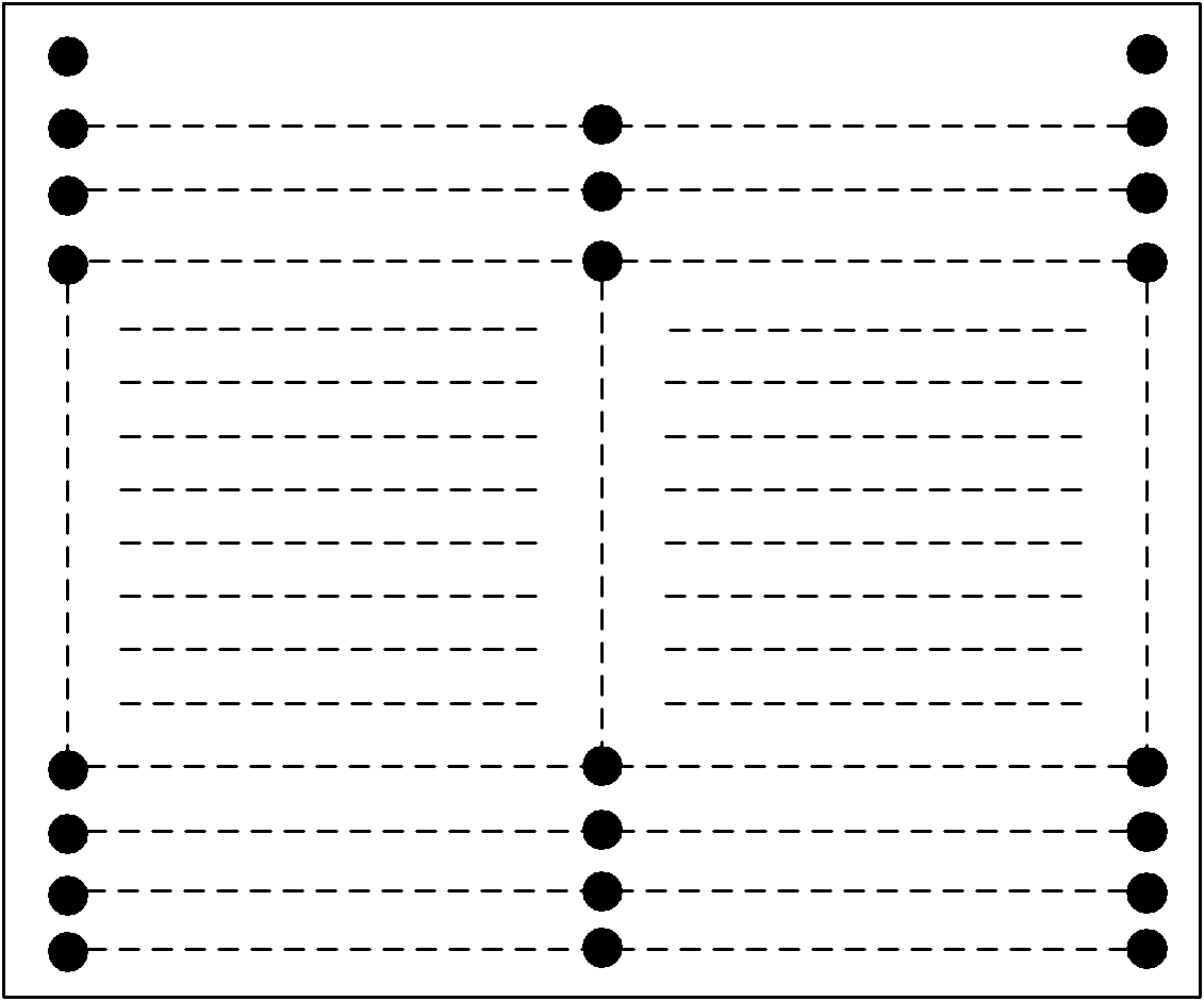
[0031] In step S20, the scattering corrector is placed between the object to be scanned and the detector, and an equiangular circular scan is performed to obtain an attenuation projection image. In this example, if figure 2 As shown, the scattering corrector (scattercorrection device, SCD) is to embed small balls in the thin plate, and the absorption coefficient of the thin plate is smaller than that of the small balls. The pellets are distributed in a checkerboard pattern in the sheet. The size of the scatter correc...


PUM


Abstract

A scattering correction method of a CT system includes the following steps: obtaining a light field image; placing a scattering corrector between an object to be scanned and a detector for performing equal-angle cycle scanning to obtain a damped projection image; respectively performing the equal-angle cycle scanning on the object to be scanned and the scattering corrector to obtain a projection image collection and a scattering correction image; generating a scattering strength distribution graph according to the light field image, the scattering corrector image and the damped projection image; and obtaining a corrected projection image collection according to difference between the projection image collection and the scattering strength distribution graph. In the scattering correction method of the CT system and the CT system, influence on the scattering is removed through placing the scattering corrector between the object to be scanned and the detector, so that processing time and processed data quantity are greatly reduced, and efficiency and precision are effectively improved.

Description

【Technical field】 [0001] The invention relates to a simulation imaging technology, in particular to a scattering correction method of a CT system and a CT system. 【Background technique】 [0002] CT imaging technology (computed tomography, electronic computer X-ray tomography technology) has multiple functions of X-ray fluoroscopy, photographing and volume imaging of the treatment position. A ray consists of two components, the initial ray and the scattered ray. The initial rays generate signals and then generate images, and the scattered rays generate noise and image artifacts, such as cupping artifacts and streak artifacts, which reduce the contrast of the projected image and result in inaccurate reconstructed CT values. Linear array detectors are used in fan-beam CT systems, which are only affected by one-dimensional scattering and will not generate a large amount of scattered rays. A very good scattering suppression effect can be achieved by installing a collimator. Howe...

Claims


Application Information

Patent Timeline
Patent Type & Authority Applications(China)
IPC IPC(8): A61B6/03
CPCA61B6/4291A61B6/483
Inventor 胡战利夏丹桂建保邹晶戎军艳张其阳郑海荣
Owner SHENZHEN INST OF ADVANCED TECH CHINESE ACAD OF SCI
Why Eureka
Try Eureka