Eureka AIR delivers breakthrough ideas for toughest innovation challenges, trusted by R&D personnel around the world.

Compound electrode plate and PECVD deposition box and PECVD system

A composite electrode, deposition box technology, applied in gaseous chemical plating, metal material coating process, coating and other directions, can solve the problem of difficulty in flexible adjustment of electrode plate spacing, and achieve the effect of uniform discharge

Active Publication Date: 2011-03-23
SHEN ZHEN TRONY SCI & TECH DEV CO LTD
View PDF3 Cites 8 Cited by
  • Summary
  • Abstract
  • Description
  • Claims
  • Application Information

AI Technical Summary

Problems solved by technology

The US patent "Low-Cost and High Performance Solar Cell Manufacturing Machine" (Pub. No.: 2007 / 0137574 A1) adopts a method of single-point feeding and drilling holes on the electrode plate to improve the uniformity of electrode plate discharge and film preparation. However, the position of the electrode plates in this patent is fixed and the distance between the electrode plates is difficult to adjust flexibly

Method used


Image

  • Compound electrode plate and PECVD deposition box and PECVD system
  • Compound electrode plate and PECVD deposition box and PECVD system
  • Compound electrode plate and PECVD deposition box and PECVD system

Examples


Embodiment 1

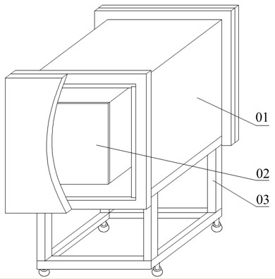
[0020] figure 1 It is a schematic diagram of the appearance of the PECVD system equipment of the first embodiment. Such as figure 1 As shown, the PECVD system related to the present invention is mainly composed of a vacuum chamber 01 , a deposition box 02 and a support 03 .

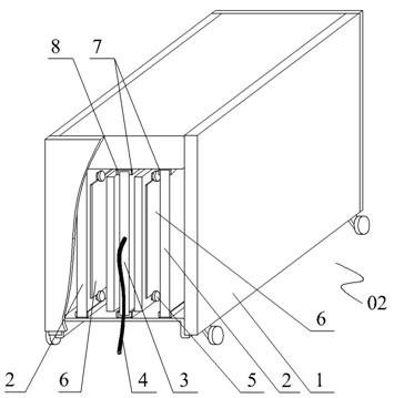
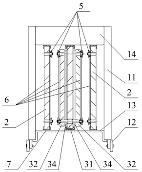
[0021] figure 2 It is a schematic diagram of the appearance of the PECVD deposition box of the first embodiment. As shown in the figure, the deposition box 02 is composed of a deposition box casing 1 , an anode electrode plate 2 , a composite electrode plate 3 as a cathode, a fixing slot 7 and an insulating slot 8 . The composite electrode plate 3 and the anode electrode plate 2 as the cathode are placed in the middle of the upper fixing plate 14 and the lower fixing plate 13 of the deposition box shell 1, respectively fixed in the fixing slots 7 welded thereon. An insulating groove 8 is installed in the fixing groove 7 where the fixing piece 31 contained in the composite electrode plate 3 is plac...

Embodiment 2

[0025] The PECVD system of the present embodiment, the PECVD deposition box and the composite electrode plate are the same as those of Embodiment 1, the difference is that the movable sheet of the composite electrode plate remains non-parallel to a certain extent (such as Figure 7 As shown), so that the anode plate and the cathode plate are not parallel, the distance between the upper electrode plate is 25mm, and the distance between the lower electrode plate is 20mm. The uneven performance of the electrode plate discharge balances the inhomogeneity of the air flow, and finally a relatively uniform film is prepared.

Embodiment 3

[0027] The PECVD system of the present embodiment, the PECVD deposition box and the composite electrode plate are the same as those of Embodiment 1, the difference is that a plurality of composite electrode plates 3 as cathodes can be arranged alternately with a plurality of anode electrode plates 2 to form an electrode plate array ( Such as Figure 8 shown). The electrode plate array technology can significantly improve the efficiency of PECVD film preparation and reduce the cost.


PUM


Abstract

The invention provides a compound electrode plate. The invention is characterized in that the compound electrode plate comprises a fixed plate and two movable plates; wherein the movable plates are arranged at the two sides of the fixed plate, and the distance between the movable plates and the fixed plate can be adjusted. The movable plates can be parallel with the fixed plate or can not be parallel with the fixed plate. The invention also provides a PECVD deposition box and a PECVD system which apply the compound electrode plate. The PECVD system applying the compound electrode plate can flexibly adjust the space of electrode plates, and uniform discharge between electrode plates is realized.

Description

technical field [0001] The invention relates to the preparation equipment of PECVD films and related devices in the fields of thin film solar cells, flat panel displays, etc., in particular to the preparation equipment of PECVD films with composite electrode plates and related devices. Background technique [0002] PECVD (Plasma Enhanced Chemical Vapor Deposition) generates active groups through plasma discharge to promote the reaction of film formation, which can significantly reduce the temperature of CVD film preparation, so that some CVD coating reactions that originally need to be carried out at high temperatures can be performed at lower temperatures. next. [0003] The equipment used in PECVD includes electrode plates, and the distance between the electrode plates significantly affects the properties of the films prepared by PECVD. If the distance between electrode plates is too large, the speed of film deposition will be significantly reduced, and the quality of fil...

Claims


Application Information

Patent Timeline
Patent Type & Authority Applications(China)
IPC IPC(8): C23C16/50
Inventor 李毅虞晓江胡盛明李志坚
Owner SHEN ZHEN TRONY SCI & TECH DEV CO LTD
Why Eureka
Eureka Blog
Learn More