
Antenna reflection surface fitting method

A reflector, antenna technology, applied in antennas, measuring devices, instruments, etc., can solve problems such as incomplete parameter satisfaction

Inactive Publication Date: 2013-08-21
NANJING INST OF ASTRONOMICAL OPTICS & TECH NAT ASTRONOMICAL OBSE
View PDF2 Cites 0 Cited by
  • Summary
  • Abstract
  • Description
  • Claims
  • Application Information

AI Technical Summary

Problems solved by technology

The former two are only suitable for the case where the deformation and rotation angle are very small; although the third method can fit the surface at any position in space, the obtained parameters do not completely satisfy the original form of the conditional expression

Method used


Image

  • Antenna reflection surface fitting method
  • Antenna reflection surface fitting method
  • Antenna reflection surface fitting method

Examples


Embodiment Construction

[0044] The present invention will be further described below in conjunction with the accompanying drawings and embodiments.

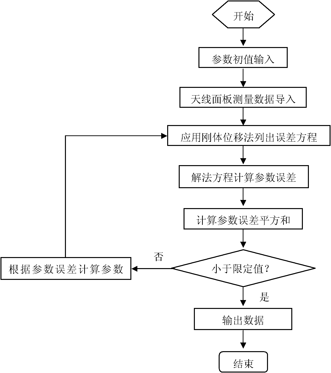
[0045] Applying the present invention to the measurement and fitting of the reflective surface of the radio telescope can well reflect the error of the panel, and its realization can be realized by software programming, such as figure 2 As shown, the antenna reflector fitting method includes the following steps:

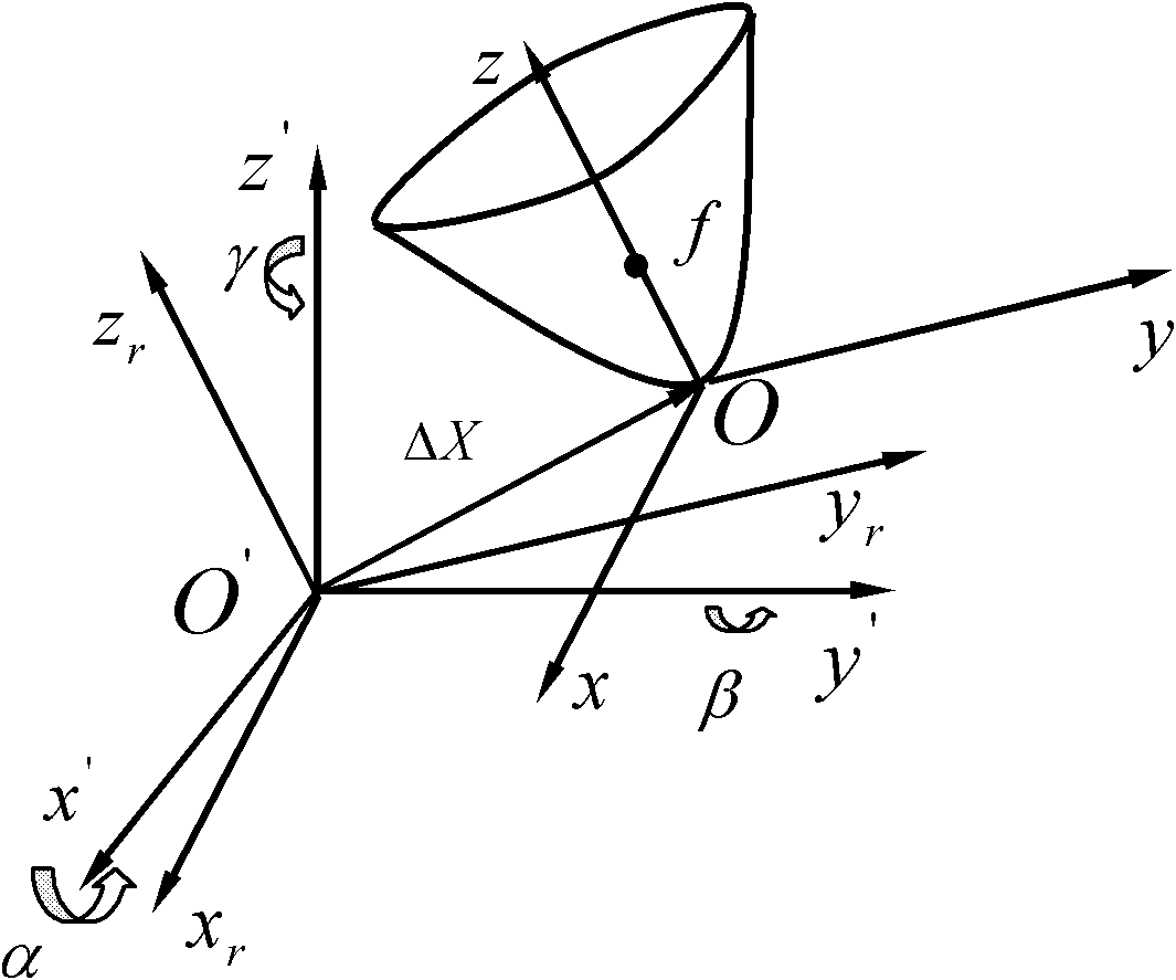
[0046] 1) Treat the paraboloid as a rigid body, in the standard coordinate system (oxyz) and the measurement coordinate system (o'x'y'z'), take the origin in the standard coordinate system as the reference point, and use the rotation motion plus the translation motion To describe the change of the position and orientation of the paraboloid, the attitude of the paraboloid is considered to be the fixed point rotation of the standard coordinate system, the deformation point and the corresponding point on the best fitting paraboloid around the or...


PUM


Abstract

The invention relates to an antenna reflection surface fitting method. The method comprises the following steps of: 1) by taking a paraboloid as a rigid body and an original point in a standard coordinate system as a reference point, describing the change of a position and a direction of the paraboloid by using rotary motion and translational motion in the standard coordinate system and a measurement coordinate system, and inputting the initial values of fitting parameters by selecting rotation angles (a, b), translation (Dx, Dy and Dz) and a focal length f of the paraboloid as the fitting parameters of the rigid body; 2) importing measured data of a measured point on the paraboloid; and 3) writing a parabolic equation in the format of a vector, converting a coordinate of the measured point in the measurement coordinate system into that in the standard coordinate system, working out the equation of the measured point which is converted to that in the standard coordinate system, substituting the measured point which is converted to that in the standard coordinate system into a standard equation of the paraboloid for comparison, working out an error equation, linearizing the error equation, and working out a parameter value according to a non-linear least square principle to obtain the optimum parabolic equation.

Description

technical field [0001] The invention relates to a parabolic antenna, in particular to an antenna reflection surface fitting method, which is used for optimal paraboloid fitting, reflection surface measurement, installation and debugging of the antenna reflection surface of a radar or a radio telescope. Background technique [0002] Parabolic antennas are widely used in radar and radio astronomy. The surface shape of the antenna should maintain its accurate shape during processing and use. The difference between the actual surface shape of the antenna and its ideal and accurate shape is the surface error. The size of the shape error directly affects the performance of the antenna. In order to accurately calculate the actual error of the reflective surface, it is generally necessary to perform the best paraboloid fitting on the deformed reflective surface. Therefore, how to accurately and quickly calculate the surface shape error through the measurement data is very benefici...

Claims


Application Information

Patent Timeline
Patent Type & Authority Patents(China)
IPC IPC(8): G01B21/20H01Q15/16
Inventor 杨德华马增祥李国平
Owner NANJING INST OF ASTRONOMICAL OPTICS & TECH NAT ASTRONOMICAL OBSE
Learn More