Motor cooling system and motor with same

A technology for motor cooling and cooling system, which is applied in cooling/ventilation devices, electrical components, electromechanical devices, etc., can solve the problems of complex motor heat dissipation structure, complicated installation and maintenance, etc., to simplify the structure, reduce production costs, and improve efficiency. Effect

Inactive Publication Date: 2011-03-23
SHENZHEN INOVANCE TECH
View PDF7 Cites 6 Cited by
  • Summary
  • Abstract
  • Description
  • Claims
  • Application Information

AI Technical Summary

Problems solved by technology

[0005] The technical problem to be solved by the present invention is to provide a motor cooling system and a motor with the cooling syst

Method used


Image

  • Motor cooling system and motor with same
  • Motor cooling system and motor with same
  • Motor cooling system and motor with same

Examples


Example Embodiment

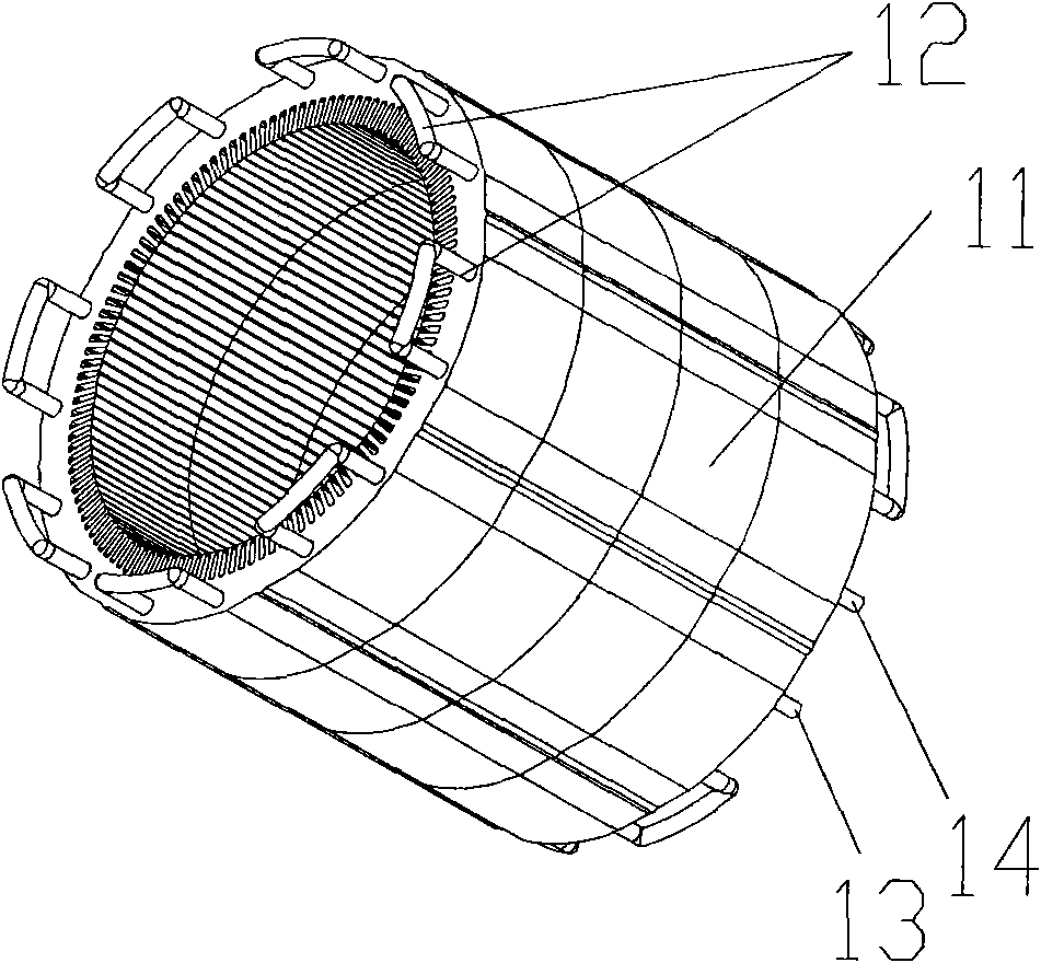
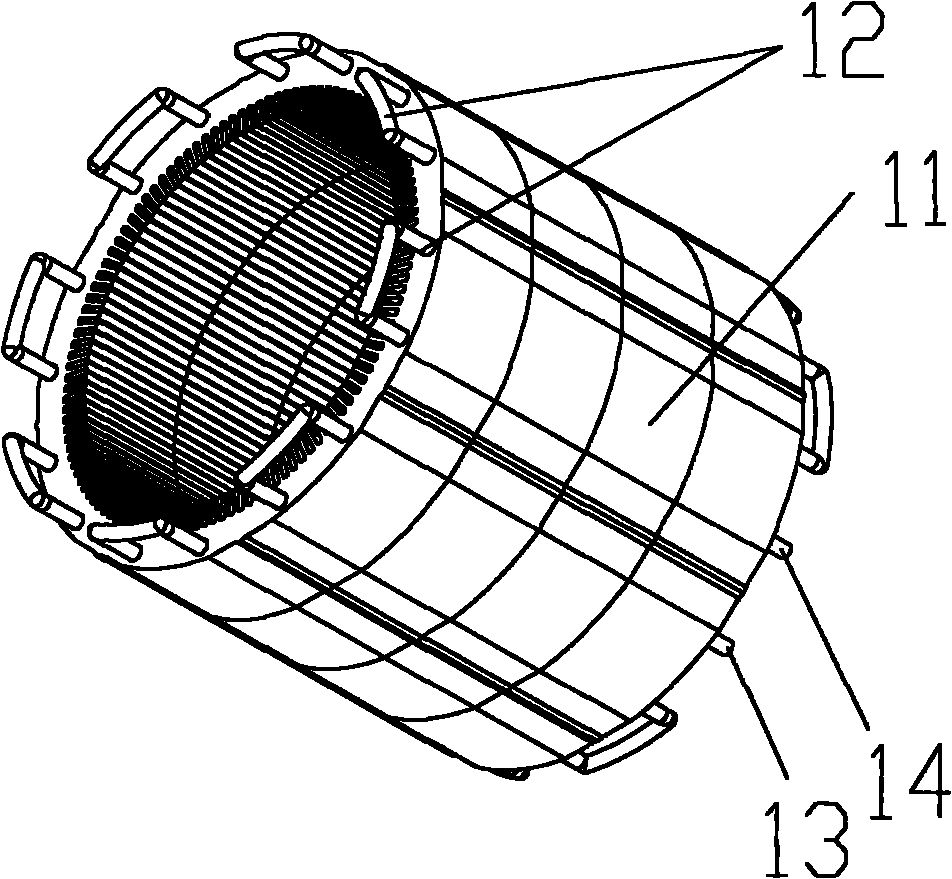
[0020] The invention realizes the cooling of the entire stator iron core by arranging a cooling circuit in the stator iron core, so that the cooling liquid flows in the cooling circuit to take away the heat generated when the motor is running.

[0021] like figure 1 As shown, it is a schematic structural diagram of an embodiment of the motor cooling system of the present invention. The system includes a stator core 11 and a cooling circuit 12, wherein the cooling circuit 12 is penetrated in the stator core 11 and has:

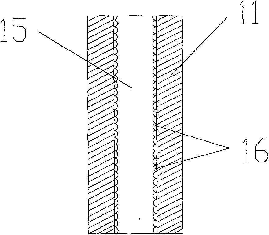
[0022] Specifically, in one embodiment, the stator core 11 is provided with a plurality of (for example, figure 1 The 16 through holes shown in ) are spaced apart from each other (for example, along the direction of the rotor axis. The plurality of through holes are located at different positions on the circumference of the stator core and are evenly distributed).

[0023] The cooling circuit 12 is provided through a plurality of through holes in the stator c...


PUM


Abstract

The invention relates to a motor cooling system which comprises a stator core and a cooling circuit, wherein a plurality of mutually separated axial through holes are arranged on the stator core, and the cooling circuit passes through the plurality of through holes on the stator core, and comprises a coolant inlet and a coolant outlet. The invention also discloses a motor with the cooling system. In the invention, by the cooling circuit passing through the stator core, the coolant in the cooling circuit flows through the whole stator core and carries away heat, thereby realizing cooling the whole stator core.

Description

technical field [0001] The invention belongs to the technical field of motors, in particular to a motor cooling system and a motor with the cooling system. Background technique [0002] At present, the motors used in industry, especially the high-power motors, will cause the motor to heat up due to the iron loss of the iron core in the alternating magnetic field, the copper loss of the winding and other stray losses during the power-on operation. The increase of motor temperature will also hinder the improvement of motor power, because the temperature directly affects the performance index and reliability of the motor. [0003] Except for a small number of motors that use natural cooling, most of the high-power motors currently use a cooling structure. For example, by means of forced convection heat transfer (the heat transfer capacity of forced convection is generally 3-5 times higher than that of natural convection heat transfer), specifically, an axial flow fan coaxial w...

Claims


Application Information

Patent Timeline
IPC IPC(8): H02K9/19H02K1/20
Inventor 刘惠敏齐剑章正昌薛斌峰
Owner SHENZHEN INOVANCE TECH
Why Eureka
Try Eureka