Method for monitoring channel state in real time by measuring optical power on line

A channel status, real-time monitoring technology, applied in transmission monitoring/test/fault measurement systems, electromagnetic wave transmission systems, electrical components, etc., can solve the problems of wasting storage resources and low precision, and achieve the effect of saving storage resources and high precision

Inactive Publication Date: 2011-03-23
STATE GRID ELECTRIC POWER RES INST
View PDF3 Cites 6 Cited by
  • Summary
  • Abstract
  • Description
  • Claims
  • Application Information

AI Technical Summary

Problems solved by technology

However, this measurement method based on the look-up table not only wastes storage resources, but also has low accuracy (±1dBm)

Method used


Image

  • Method for monitoring channel state in real time by measuring optical power on line
  • Method for monitoring channel state in real time by measuring optical power on line
  • Method for monitoring channel state in real time by measuring optical power on line

Examples


Embodiment Construction

[0028] The present invention will be further described in detail below with reference to the accompanying drawings and examples.

[0029] (1) Hardware implementation scheme

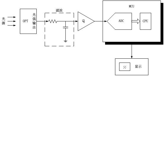
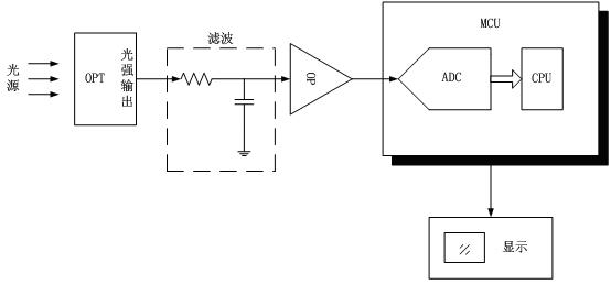
[0030] A: The light intensity detection and conversion circuit is integrated in the optical module at the receiving end: when performing optical power measurement, it is necessary to monitor the light intensity signal of the optical fiber channel. The light intensity signal is provided by the light detection circuit. The working principle of this circuit is a photodiode After receiving the optical signal in the optical fiber, a current signal I corresponding to the light intensity is generated. The current signal I is converted into a voltage signal U by the I-U conversion circuit formed by the operational amplifier and output. This part of the circuit is integrated in the optical module.

[0031] B: Establish an A / D conversion circuit, and adopt a segmented amplification method to adopt different propor...


PUM


Abstract

The invention discloses a method for monitoring channel state in real time by measuring optical power on line, which comprises the following steps of: (1) measuring an optical power-optical intensity curve table of an optical module in advance, and storing in a microprogrammed control unit (MCU); (2) integrating an optical intensity detection and conversion circuit in the optical module, establishing an A/D conversion circuit, and ensuring the measurement accuracy of A/D conversion on small signals by adopting a segmental amplification mode; (3) obtaining an A/D conversion result, and calculating an optical power value by adopting curve fit technology; and (4) establishing a perfect channel state monitoring and warning mechanism according to the optical power measuring result and the change conditions. The method for measuring and calculating the optical power on line fulfills the aim of detecting the optical power in real time on line under the condition of not disconnecting a fiber channel.

Description

technical field [0001] The invention relates to an optical fiber communication system for relay protection of a power system, in particular to a method for realizing real-time monitoring and alarming of the channel state through online measurement of optical power. Background technique [0002] At present, optical fiber communication systems are widely used in power system relay protection to complete data communication. Optical fiber loss is an important parameter that reflects the technical indicators of optical fiber communication, and is an important factor that determines the transmission distance, transmission stability and reliability of optical fiber transmission networks. Therefore, real-time monitoring of optical fiber loss is beneficial to ensure the correct transmission of information in optical fiber communication and the normal operation of the entire relay protection system. [0003] The common method of fiber loss inspection is to use the cutting method or in...

Claims


Application Information

Patent Timeline
Patent Type & Authority Applications(China)
IPC IPC(8): H04B10/08H04B10/12H04B10/07
Inventor 吴通华俞拙非周华良张宏波姚吉文郑玉平
Owner STATE GRID ELECTRIC POWER RES INST
Why Eureka
Try Eureka