Built-in spiral cyclone separator

A cyclone separation device and spiral technology, applied in suction filters and other directions, can solve the problems of complicated operation, harsh screeching, heavy cyclone separator, etc., and achieve the effects of reducing airflow noise, eliminating harsh screeching, and reducing pressure loss.

Inactive Publication Date: 2011-03-30
LG ELECTRONICS (TIANJIN) APPLIANCES CO LTD
View PDF0 Cites 11 Cited by
  • Summary
  • Abstract
  • Description
  • Claims
  • Application Information

AI Technical Summary

Problems solved by technology

It is necessary to go through the above 3 steps to dump the dust, so the operation is cumbersome
[0010] 2. In addition, the cyclone separator is heavy, and there is no handle for easy removal, so the operation is extremely difficult
[0011] 3. The cyclone dust collection device in the prior art has a complex structure and is difficult to clean
[0012] 4. At present, when the suction rate and efficiency performance test of a single dust collection bucket is performed, due to the large air velocity and structure, the noise is very loud, and it is accompanied by harsh screams

Method used


Image

  • Built-in spiral cyclone separator
  • Built-in spiral cyclone separator
  • Built-in spiral cyclone separator

Examples


Embodiment Construction

[0039] The present invention will be described in detail below with reference to the drawings and examples.

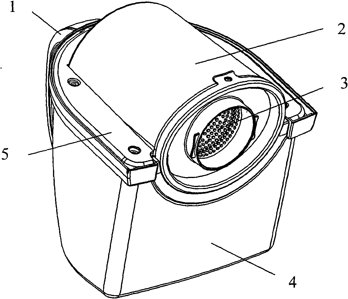
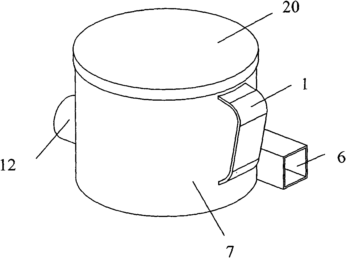
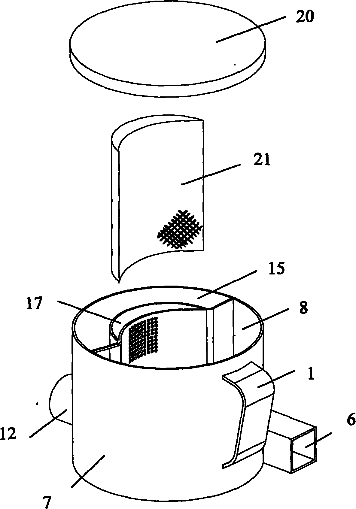
[0040] figure 2 It is a three-dimensional view of the built-in spiral cyclone separation device of the present invention; image 3 It is an exploded view of the structure of the built-in spiral cyclone separation device of the present invention; Figure 4 It is the internal structure diagram of the present invention without upper cover and filter sponge installed; Figure 5 It is a top view of the built-in spiral cyclone separation device of the present invention; Image 6 Yes Figure 5 A-A sectional view of ; Figure 7 It is a top view of another direction of the present invention; Figure 8 Yes Figure 7 The B-B section view.

[0041] The present invention has a built-in spiral cyclone separation device, such as Figure 2 to Figure 8 As shown, the built-in spiral cyclone separation device consists of a circular dust collection bucket 7 with a handle 1, an up...


PUM


Abstract

The invention provides a built-in spiral cyclone separator, comprising a handle, an airflow inlet, a dust collection barrel, an upper cover, an air outlet formed at one side of the lower part of the round dust collection barrel, a cyclone chamber formed in the round dust collection barrel, a crescent exhaust chamber, a dust collection chamber, and a filtration sponge in the exhaust chamber. The cyclone chamber is formed by the space between the inner wall of the round dust collection barrel and the bent side wall of the round dust collection barrel; the cyclone chamber is internally provided with a spiral staircase, wherein the lower end of the spiral staircase is connected with the airflow inlet and rises spirally; one end of the cyclone chamber is enclosed by a baffle while the other end forms a dust falling opening at the top of the spiral staircase; the crescent exhaust chamber is formed by the space between the side wall and a separation wall, the curvature of the separation wall is less than that of the side wall and the two ends of the separation wall is connected with the side wall, and a plurality of outer meshes are arranged on the side wall; the dust collection chamber is formed by the other space of the dust collection barrel; and the airflow inlet is formed at the lower part of the dust collection barrel and is tangent to the wall of the dust collection barrel. The built-in spiral cyclone separator reduces the airflow noise and eliminates the harsh shriek, and has the advantages of compact and simple structure, high separation efficiency, large dust collection amount, and simple and easy operation.

Description

technical field [0001] The invention belongs to the field of vacuum cleaners, in particular to a single-separation system with a compact and simple structure, high separation efficiency, reduced airflow noise, elimination of piercing sound, large dust collection capacity, and a built-in spiral cyclone separation device that is easy to operate. Background technique [0002] Vacuum cleaner is a kind of household appliance for indoor cleaning and sanitation, which is used to remove dust from floors, carpets, walls, furniture, clothing and various gaps. Generally speaking, a vacuum cleaner mainly includes a suction device and a suction pipeline. The suction device mainly formed by a motor and a fan is arranged in the body. The suction pipeline includes a suction head and a suction pipe. The air port communicates with the air inlet in the body through the telescopic tube and flexible pipe of the suction pipe. When the vacuum cleaner is running, the motor drives the impeller of t...

Claims


Application Information

Patent Timeline
Patent Type & Authority Applications(China)
IPC IPC(8): A47L9/16
Inventor 肖宗亮刘明明马哲
Owner LG ELECTRONICS (TIANJIN) APPLIANCES CO LTD
Why Eureka
Try Eureka