Strong convection structure on heat treatment furnace

A heat treatment furnace and strong convection technology, applied in heat treatment furnaces, heat treatment equipment, furnaces, etc., can solve the problems of low yield of broken bonds, complicated mechanism and operation process, and unreachable heat exchange area, etc., to increase the heat exchange area , good heat exchange effect, uniform high-speed flow effect

Inactive Publication Date: 2011-03-30
SUZHOU ZHONGMENZI TECH
View PDF3 Cites 10 Cited by
  • Summary
  • Abstract
  • Description
  • Claims
  • Application Information

AI Technical Summary

Problems solved by technology

[0002] The existing high-vacuum heat treatment furnace does not have an air circulation device. The furnace shell has a double-layer structure, and the water cooling is used between the layers. The air in the furnace does not convect. The effect is not good and the heat exchange area is limited and the ideal cooling rate cannot be achieved, resulting in an extremely low yield of broken bonds

Method used


Image

  • Strong convection structure on heat treatment furnace
  • Strong convection structure on heat treatment furnace
  • Strong convection structure on heat treatment furnace

Examples


Embodiment Construction

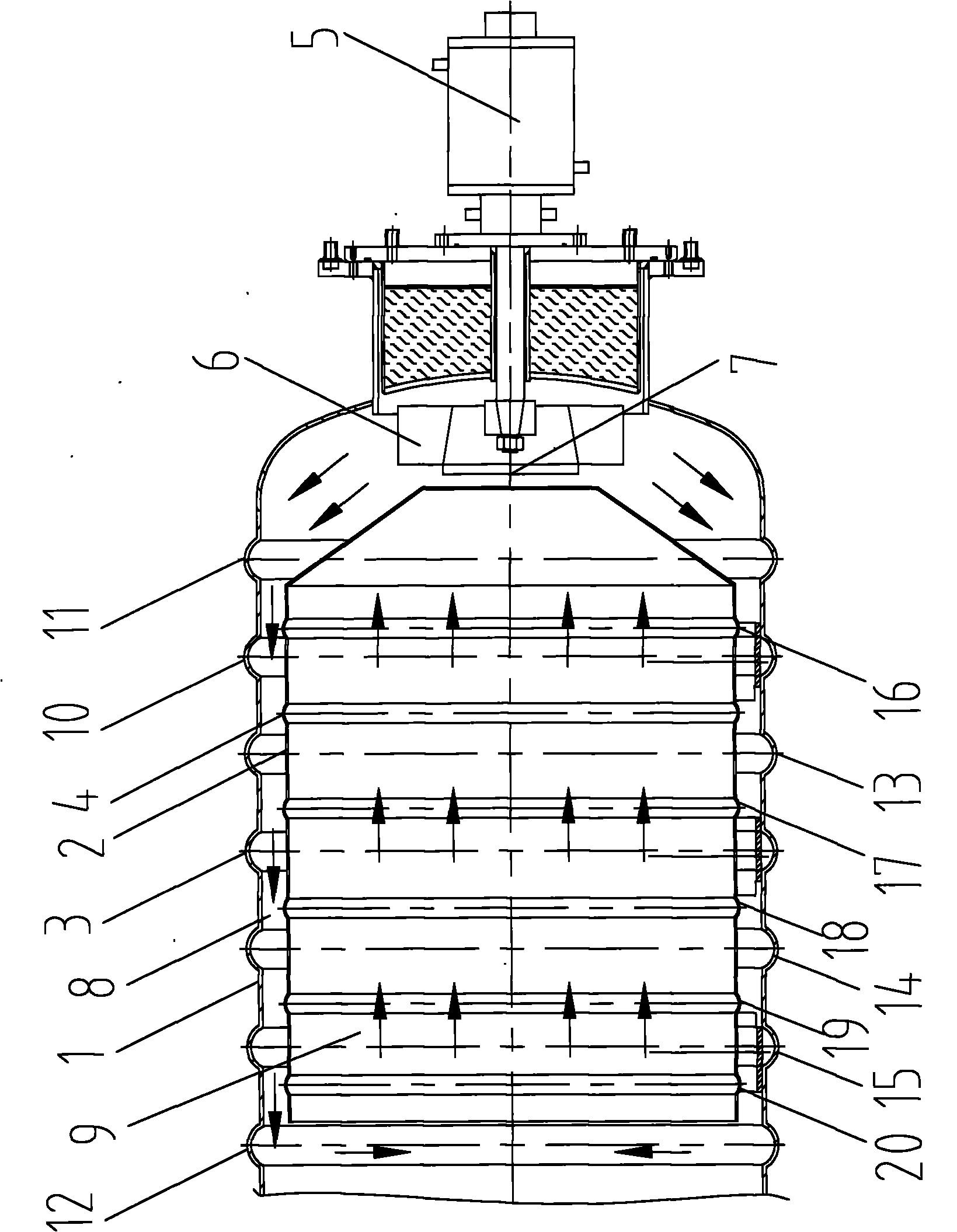
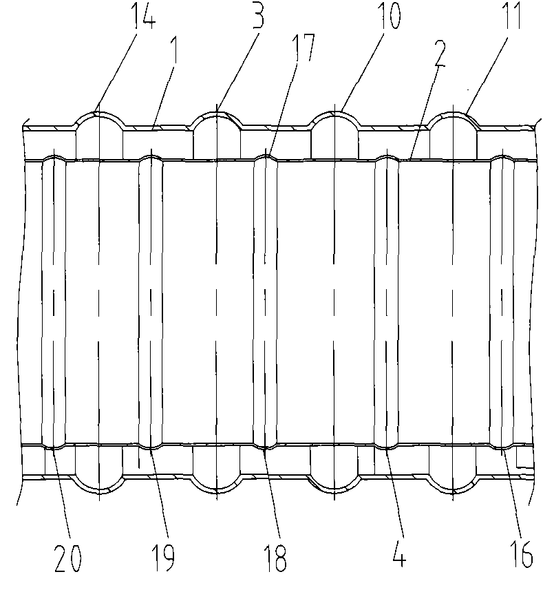
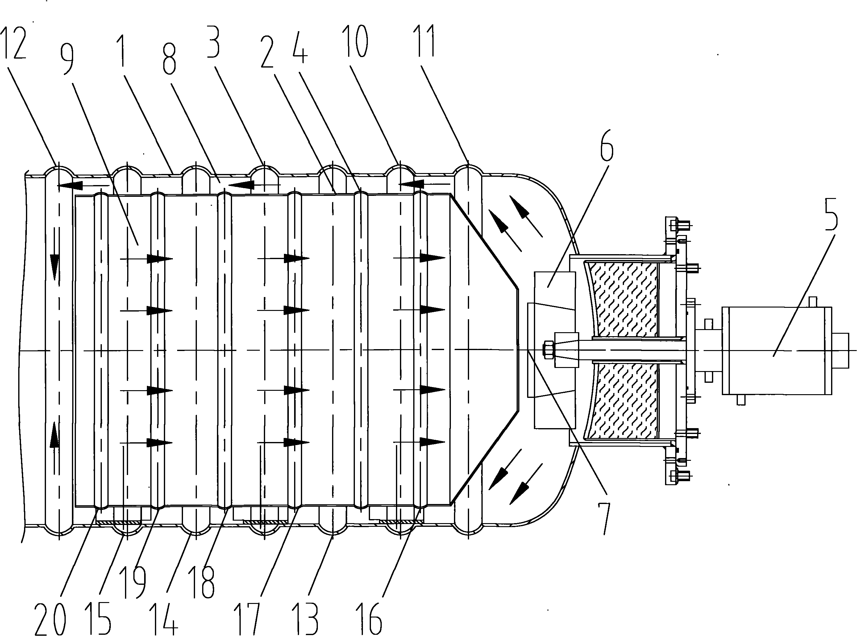
[0010] see figure 1 As shown, the interior of the furnace 1 with an inner cavity is provided with an air guide tube 2 with an inlet at the other end and an outlet at the other end, and the blades 6 of the centrifugal fan 5 are sealed in the furnace 1 through the furnace 1 mouth, and the furnace 1. The air guide tube 2 and the centrifugal fan 5 are coaxially designed. The inner peripheral surface of the furnace 1 is extruded outward to form a plurality of annular grooves 3, 10, 11, which are arranged at intervals along the axial direction on the inner surface. 12, 13, 14, 15, the inner peripheral surface of the guide tube 2 is extruded outward to form a plurality of annular protrusions arranged at intervals on the outer surface 4, 16, 17, 18, 19, 20, the outlet of the guide tube 2 Aiming at the axial suction port 7 of the centrifugal fan 5, an air supply channel 8 communicating with the inlet is formed between the furnace liner 1 and the guide tube 2, and a return channel conne...


PUM


Abstract

The invention discloses a strong convection structure on a heat treatment furnace. The convection structure comprises a furnace pipe, an air guide cylinder and a centrifugal fan, wherein the internal peripheral surface of the furnace pipe is outwards extruded on the inner surface of the same to form a plurality of ring-shaped grooves, the internal peripheral surface of the air guide cylinder in the furnace pipe is outwards extruded on the external surface of the furnace pipe to form a plurality of ring-shaped bulges, the vanes of the centrifugal fan arranged in the furnace pipe extend into the furnace pipe hermetically through the port of the furnace pipe, and gas inside the furnace can form high-speed strong convection under the effect of the centrifugal fan. The convection structure on the heat treatment furnace can ensure that gas inside furnace is more uniform in distribution, the cooling speed is faster, and the finished product rate of forgings is improved.

Description

technical field [0001] The invention relates to a strong convection structure on a heat treatment furnace. Background technique [0002] The existing high-vacuum heat treatment furnace does not have an air circulation device. The furnace shell has a double-layer structure, and the water cooling is used between the layers. The air in the furnace does not convect. The effect is not good and the heat exchange area is limited and the ideal cooling rate cannot be achieved, resulting in an extremely low yield of broken bonds. Contents of the invention [0003] The present invention is a convective cycle structure of a multifunctional heat treatment furnace for hydrogen infiltration and vacuum dehydrogenation of large cross-section titanium alloy forgings. The purpose of the present invention is to provide a heat treatment that can form a high-speed strong convection environment in the furnace and increase the heat exchange area. Convection structure on the furnace. [0004] In...

Claims


Application Information

Patent Timeline
Patent Type & Authority Applications(China)
IPC IPC(8): C21D9/00C22F1/02C22F1/18
Inventor 宋思科蒋根明马小青
Owner SUZHOU ZHONGMENZI TECH
Why Eureka
Try Eureka