
Lock screw

A screw and anti-loosening technology, which is applied in the direction of screws, nuts, bolts, etc., can solve problems such as deviation of fit clearance, unstable operation, damage to screws and other parts, etc., to achieve increased return torque, effective anti-loosening function, The effect of eliminating the coefficient of friction

Active Publication Date: 2013-01-09
KOFU SEIBYO
View PDF2 Cites 0 Cited by
  • Summary
  • Abstract
  • Description
  • Claims
  • Application Information

AI Technical Summary

Problems solved by technology

[0004] However, the internal thread and external thread based on the Japanese Industrial Standard JIS standard have a large fit difference due to different manufacturing results, and there are many loosening problems after the screw is tightened due to different uses. Therefore, only the external thread It becomes difficult to deal with products with anti-loosening agents applied on the periphery, and at the same time, it is necessary to use small screws to correspond to various products for various developed products
[0005] In addition, in order to reliably incompletely tighten the external thread, sometimes the thread portion of the external thread is adjusted several times, and the other part is fixedly connected by a small screw. However, at this time, even if the adjusted value is entered, the Due to the gap caused by the subsequent adhesive hardening acceleration time, etc., deviation occurs, and readjustment is unavoidably required. Therefore, although it is possible to obtain a delicate value, the actual situation is that the operation is unstable.
In addition, after the external thread is tightened, it is used at high temperature, and vibrations are added, because the screw and the other parts will be damaged due to excessive tightening, so it is difficult to control the tightening.

Method used

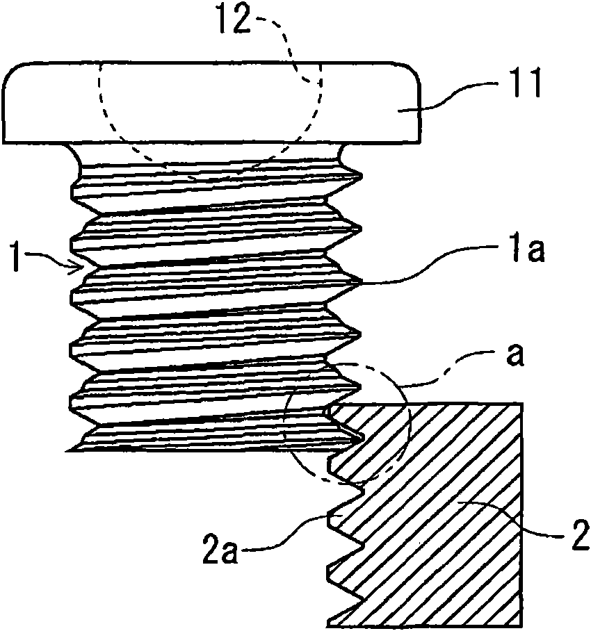
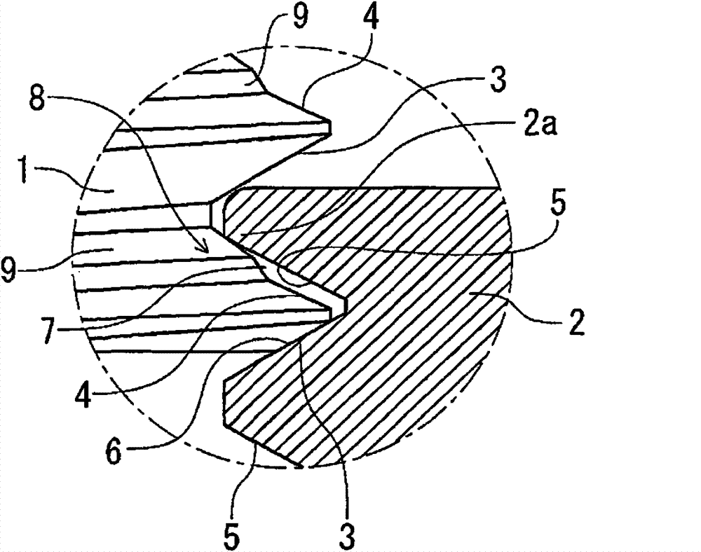
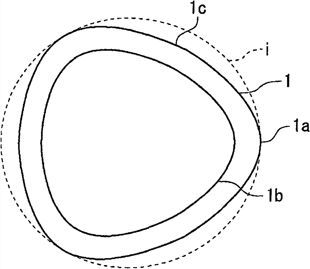

Image

  • Lock screw
  • Lock screw
  • Lock screw

Examples


Embodiment

[0036] Figure 13 Table 1 and Table 1 are graphs showing the test results of comparing the product of the present invention and the comparative product using one of the generally commercially available JIS grade 2 nuts as test workpieces, and Table 1 is a table showing the data. Figure 14 Table 2 and Table 2 are graphs showing test results in which the product of the present invention and the comparative product were compared using a product obtained by drilling a hole in an iron plate (SPCC plate t=0.8mm) and tapping it with a tap as a test workpiece. , Table 2 is a table representing its data.

[0037] In the comparison table of Table 1, one kind of JIS class 2 nut was used as the test workpiece, and the test was implemented at a screwing torque of 2.0 kgfcm. In Table 1, comparative product 1 uses ordinary small screws processed in No. 0, 2 types, 2 and 3, and comparative product 2 uses a conventional mechanical anti-loosening screw that uses the front end of the thread to...


PUM


Abstract

A lock screw is capable of being screwed easily, being used as an adjusting screw of a small screw, flexibly responding variation of temperature and fastening operation, and being of bulk production by a mechanical process at a low cost. The lock screw is used for locking when an external thread is screwed into an internal thread which has an arced triangular section, where a sloping angle of a side face on an opposite side is less than that of a side face on an advance side of the external thread, a material opening space is formed between side faces of the internal thread facing to the sideface, a projecting deflection angle part is arranged nearby an inner diameter side of the side face of the external thread on the side of the material opening space, simultaneously, when the externalthread is screwed into the internal thread, a material part being of crimp connection by the deflection angle part is formed nearby an inner diameter side of ridge of the internal thread in moving tothe material opening space, and the screw is locked by the crimp connection of side faces of the material part of the internal thread formed by the movement and the other side faces of the internal thread.

Description

technical field [0001] The present invention relates to an anti-loosening screw with an external thread screwed into an internal thread to be used as an adjusting screw or a fastening screw, in particular to an anti-loosening screw suitable for a small external thread of M2mm or less. Background technique [0002] Generally, when screwing an external thread as a small screw into a corresponding internal thread to exhibit a sufficient anti-loosening function, a small screw whose outer periphery of the external thread is chemically treated is often used. This small screw is generally processed by professionals who implement anti-loosening in another process after the thread is manufactured. In addition, users of small screws are also implementing a method of obtaining a return torque from the screw-in torque of the external thread by applying an anti-loosening agent such as an adhesive to the outer circumference of the screwed-in head. [0003] Recently, light and thin produc...

Claims


Application Information

Patent Timeline
Patent Type & Authority Patents(China)
IPC IPC(8): F16B35/04F16B33/02F16B39/30B21H3/02
Inventor 饭岛康雄
Owner KOFU SEIBYO
Learn More