
System and method for determining obstacle by using aerial view images

An image judgment and obstacle technology, applied in the field of obstacle detection systems, can solve the problems of increasing the cost of ultrasonic devices, difficult to display obstacles with high heights, difficult to meet the needs of drivers, etc., to achieve the effect of strengthening the detection range

Active Publication Date: 2011-03-30
AUTOMOTIVE RES & TESTING CENT
View PDF1 Cites 30 Cited by
  • Summary
  • Abstract
  • Description
  • Claims
  • Application Information

AI Technical Summary

Problems solved by technology

As disclosed in the patent application with the patent publication number JP2007041791 (A), a system and method for displaying a bird's-eye view image, which first uses multiple cameras to collect images around the vehicle, stitches the images into a bird's-eye view image of the surrounding field, and learns from the images Whether there are obstacles near the front, rear, left, and right of the vehicle, and in order to overcome the problem that it is difficult to display high-level obstacles at the image stitching, the patent uses four ultrasonic devices to detect the dead-angle area to solve the problem
However, although this method can overcome the above problems, it will relatively increase the cost of the ultrasonic device
[0005] Furthermore, in the conventional two-dimensional bird's-eye view surround field imaging system, the virtual viewpoint is mostly set above the vehicle. However, when the vehicle is moving forward, backward or turning, the size of the field of view of the image area in the direction the driver needs to move is also different. , but the conventional technology only uses a bird's-eye view image with a fixed virtual perspective, which is difficult to meet the driver's needs

Method used


Image

  • System and method for determining obstacle by using aerial view images
  • System and method for determining obstacle by using aerial view images
  • System and method for determining obstacle by using aerial view images

Examples


Embodiment Construction

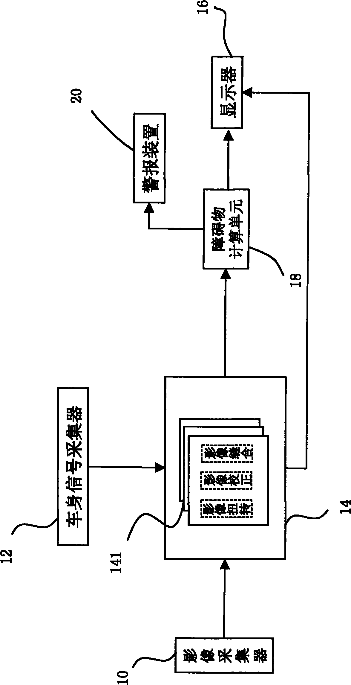
[0034] The main technical means of the present invention converts the images collected by different cameras into two independent bird's-eye-view images, and then performs a correlation comparison on the repeated regions of the two independent bird's-eye-view images, and if the comparison result has a high correlation, it is judged that the There is no high-level obstacle in the area; on the contrary, if the correlation is low, it is judged that there is a high-level obstacle. This method can accurately judge whether there is an obstacle and its position and distance.

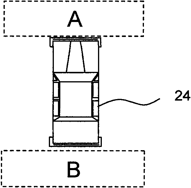
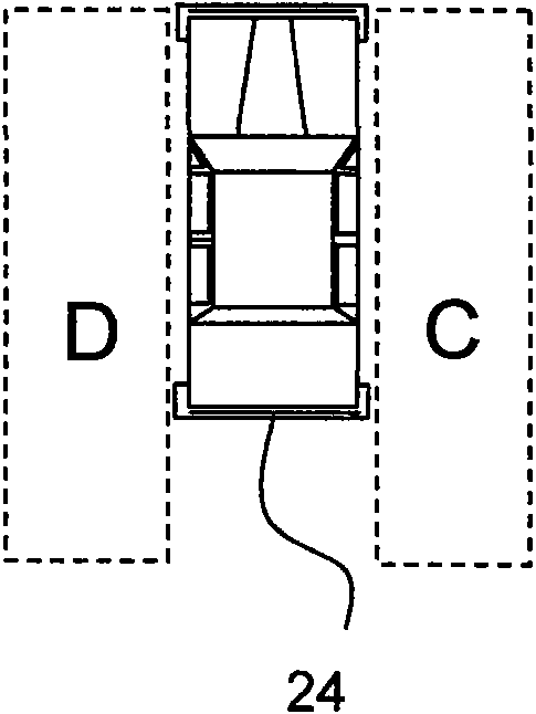
[0035] First please refer to figure 1 , is a system architecture diagram of an embodiment of the present invention. In this embodiment, six image collectors 10 installed on the vehicle are used to collect images around the vehicle body, and the images collected by each adjacent image collector 10 are The images all have partially overlapped images of the same region, which are collectively referred to as overla...


PUM


Abstract

The invention provides a system and a method for determining an obstacle by using aerial view images, relates to technology for determining the obstacle around a vehicle by aerial view image technology. A plurality of image acquisition devices which are arranged at different positions are used for acquiring a plurality of images around a vehicle body respectively, and the plurality of images are at least provided with an overlapping region; an image processor performs independent aerial view image conversion on the images; and an obstacle calculating unit compares the correlation of repeat regions of two independent aerial view images and judges whether the obstacle exists or not according to the size of the correlation. In addition, a mapping table of a group of space conversion data is constructed and comprises driving state data such as the steering wheel angle, gear or speed of the vehicle, and the like, so when the driving state is changed, a panoramic aerial view image at an appropriate viewing angle is quickly converted through the mapping table, and the position of the obstacle measured by the obstacle calculating unit is marked on the panoramic aerial view image; therefore, the safe driving of a user is facilitated.

Description

technical field [0001] The present invention relates to an obstacle detection system, in particular to an obstacle detection system used when driving a vehicle. Background technique [0002] The cost of cameras is decreasing day by day, and photographic equipment is now widely used in vehicle driving assistance, but most of them only passively provide images around the vehicle to assist drivers in avoiding accidents. Since it is difficult for the driver to monitor multiple photographic images at the same time, and the visual blind spot is still large when the traditional planar image is used for parking assistance, there are currently some companies in the industry that can use multiple cameras placed around the car body to combine the multiple images obtained. The images are integrated and converted to form a bird's-eye view image system of a virtual surround field viewed from the roof, which is more in line with the visual habits of the human eye and can further overcome t...

Claims


Application Information

Patent Timeline
IPC IPC(8): G01C11/00G01C11/06G01C3/00B60R1/00B60R21/00
Inventor 徐子建陈加增
Owner AUTOMOTIVE RES & TESTING CENT
Learn More