
Laser beam transformation shaper outputting uniform linear spots

A laser beam, uniform line technology, applied in optics, instruments, optical components, etc., can solve problems such as unfavorable surface treatment efficiency, unfavorable surface treatment uniformity, and improvement

Inactive Publication Date: 2011-03-30
BEIJING UNIV OF TECH
View PDF3 Cites 21 Cited by
  • Summary
  • Abstract
  • Description
  • Claims
  • Application Information

AI Technical Summary

Problems solved by technology

For applications such as high-precision laser polishing, high-precision laser cleaning, and high-efficiency laser-induced surface modification of materials, traditional laser beam transformation shapers often fail to achieve ideal results due to uniformity and efficiency issues, for example: " The output laser spot of the Gaussian-flat-top transform shaper is usually a circular spot, the output laser spot of the compound eye uniform beam transform shaper is usually a square spot, and the laser energy loss in the telescope system with a diaphragm is relatively large, etc. It is conducive to the improvement of surface treatment efficiency; the energy distribution of the exit laser spot of the optical waveguide uniform beam transformation shaper is usually near Gaussian distribution, which is not conducive to the improvement of surface treatment uniformity

Method used


Image

  • Laser beam transformation shaper outputting uniform linear spots
  • Laser beam transformation shaper outputting uniform linear spots
  • Laser beam transformation shaper outputting uniform linear spots

Examples


Embodiment Construction

[0033] The present invention will be further described below in conjunction with accompanying drawing:

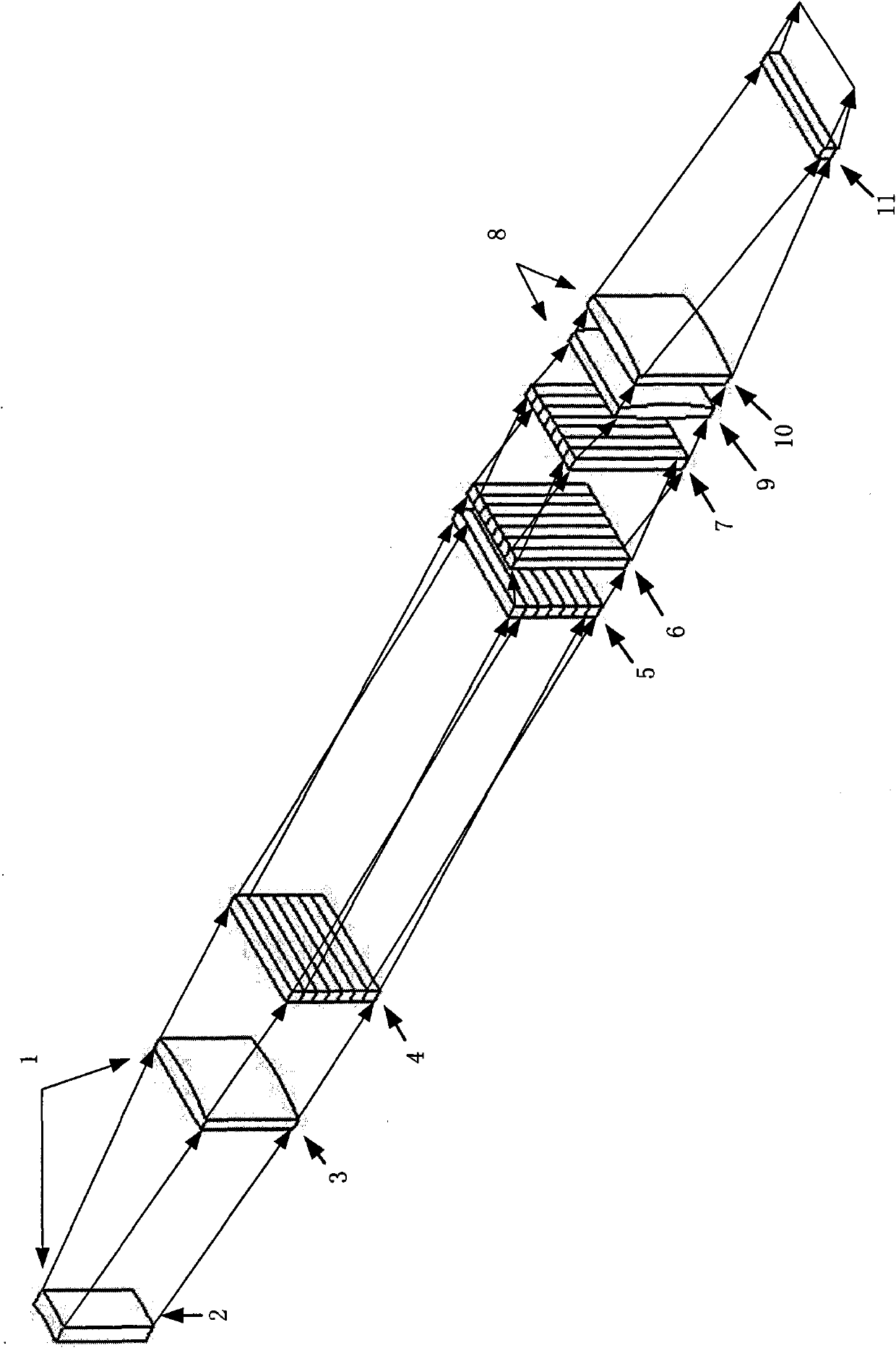
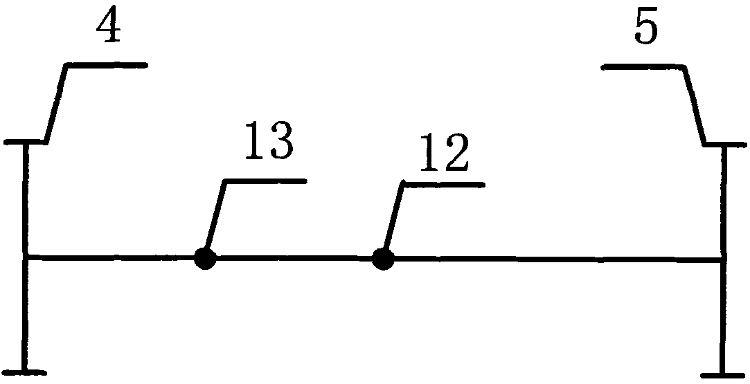
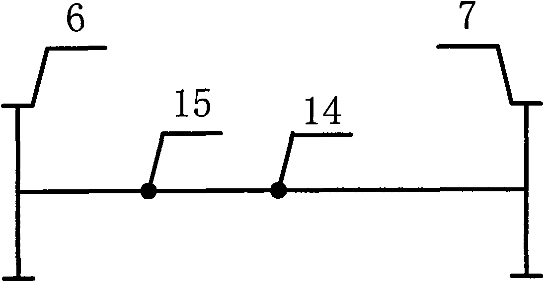
[0034] In this embodiment, the spot shape of the incident laser is rectangular (18mm × 35mm), the spot energy distribution is non-uniform distribution (18mm direction is Gaussian distribution, 35mm direction is nearly Gaussian distribution), and the central wavelength is 248nm excimer laser. Suitable for high precision laser polishing and laser cleaning. This embodiment consists of a first part 1 , a second part 4 , a third part 5 , a fourth part 6 , a fifth part 7 , a sixth part 8 and a seventh part 11 . The first part is a telescope system, which is made up of two cylindrical lenses; the second part 4, the third part 5, the fourth part 6 and the fifth part 7 are all cylindrical lens arrays, wherein the second part 4 and the third part 5 The generatrixes of the cylindrical lens array are parallel, the generatrixes of the third part 5 and the fourth part 6 are vertical, an...


PUM


Abstract

The invention discloses a laser beam transformation shaper outputting uniform linear spots, which is an optical system capable of transforming and shaping laser beams with irregular spot shapes and nonuniformly distributed energy into laser beams with uniformly distributed energy and the spot shape approaching a line, and is mainly applied to laser polishing, laser cleaning and laser induced material surface modification, and belongs to field of laser surface processing technology and application thereof. The laser beam transformation shaper comprises seven parts, namely a first part of a telescope system consisting of a plurality of circular lenses or cylindrical lenses, second, third, fourth and fifth parts consisting of a cylindrical lens array respectively provided with N cylindrical lenses, a sixth part consisting of two cylindrical lenses of which the generatrices are vertical mutually, and a seventh part consisting of cylindrical lenses or cylindrical lens combination. The laser beam transformation shaper transforms and shapes incident laser into linear laser spots with uniformly distributed spot energy, and greatly improves the efficiency of laser polishing, laser cleaningand laser induced material surface modification by matching high-speed movement of a work bench.

Description

technical field [0001] The invention is a laser beam transformation shaper whose output is uniform line spot, which is a kind of light spot with irregular shape (such as: circular, nearly circular, elliptical, nearly elliptical, square, nearly square, etc.), The laser beam with uneven energy distribution (such as: Gaussian distribution, near-Gaussian distribution, etc.) is transformed into an optical system with uniform energy distribution and a laser beam whose spot shape is approximately a line after beam transformation. It is mainly used in laser polishing, laser cleaning, laser It belongs to the field of laser surface treatment technology and its application. Background technique [0002] The laser spot required for laser surface treatment technology and its application fields is slightly different depending on the technology used. Among them, the shape of the laser spot is usually square, rectangular or approximately a line, and the energy distribution of the laser spot...

Claims


Application Information

Patent Timeline
IPC IPC(8): G02B27/09
Inventor 陈涛王桐左铁钏
Owner BEIJING UNIV OF TECH
Learn More