
Self-powered solar tracking probe

A technology for tracking the sun and detectors, applied in the field of solar energy applications, can solve the problems of reduced tracking accuracy, susceptible to scattered light, and affecting the life of photosensitive elements

Inactive Publication Date: 2011-03-30
WUXI HAOSOLAR TECH CO
View PDF3 Cites 5 Cited by
  • Summary
  • Abstract
  • Description
  • Claims
  • Application Information

AI Technical Summary

Problems solved by technology

The disadvantage of this kind of solar tracking detector is that the photosensitive elements of the four quadrants need to be driven by a precise power supply. The power supply is always added to the four photosensitive elements. The power supply voltage has nothing to do with the brightness of the sky and is easily affected by scattered light. Tracking accuracy decreases when
In addition, the loading of the power supply in rainy days and at night affects the life of the photosensitive element and wastes the driving power of the photosensitive element.

Method used


Image

  • Self-powered solar tracking probe
  • Self-powered solar tracking probe
  • Self-powered solar tracking probe

Examples


Embodiment Construction

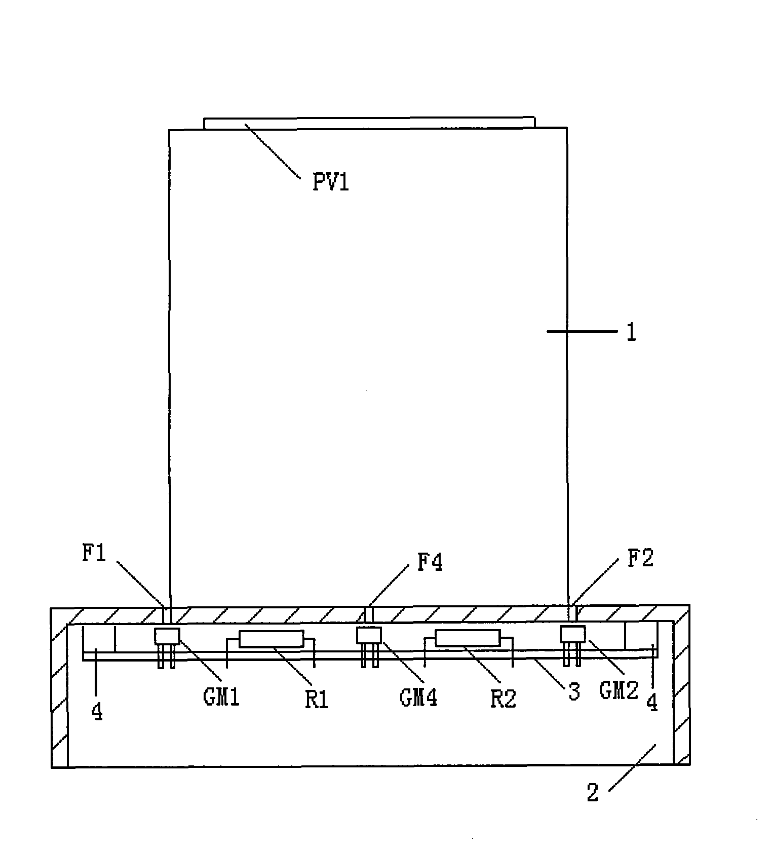
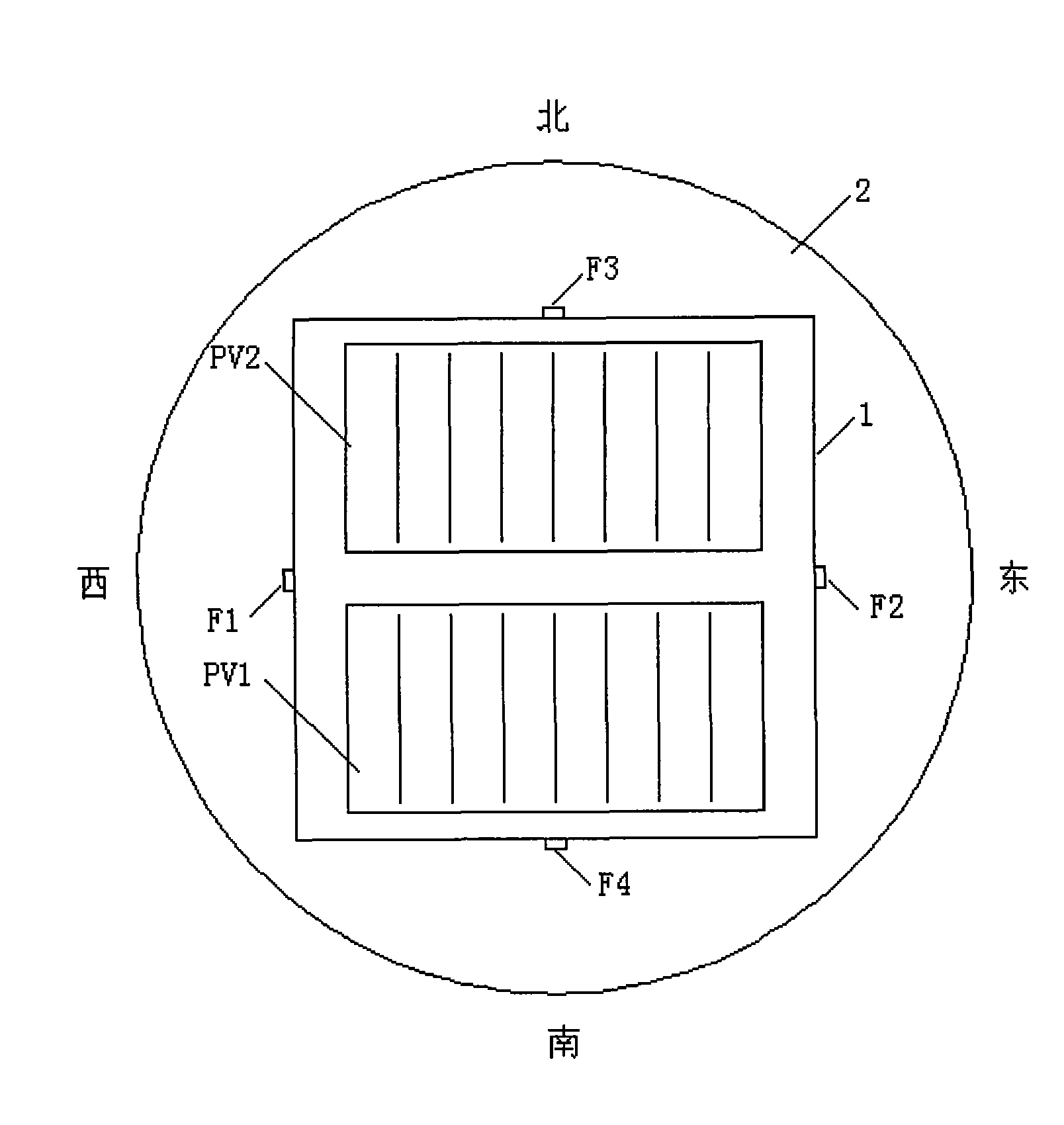
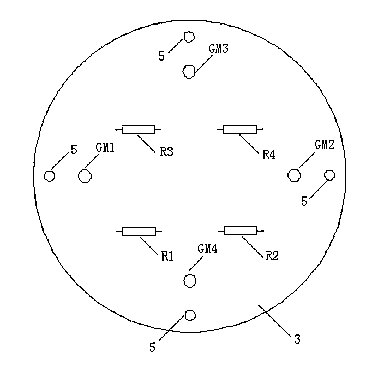
[0013] exist figure 1 In the structural diagram of the self-powered tracking sun detector of the present invention, the shading column 1 is vertically installed on the base 2, the axis of the shading column 1 is located at the center of the base 2, and the base 2 is divided into 4 areas by the shading column 1. There are four small light guide holes F1, F2, F3, F4 for detecting photoresistors GM1, GM2, GM3, and GM4 in the four directions of West, East, North, and South near the center of the bottom edge of the shading column 1. The 4 small holes F1, F2, F3, and F4 on the back correspond to 4 photoresistors GM1, GM2, GM3, and GM4, and the 4 photoresistors and the resistors R1, R2, R3, and R4 that constitute the elevation angle and azimuth angle detection circuit are installed on the base 2, the circuit board 3 is fixed on the fixing post 4 of the base 2 through the fixing hole 5. 4 photoresistors and 4 resistors form azimuth and elevation detection circuits. Two solar cells P...


PUM


Abstract

The invention provides a self-powered solar tracking probe. A shading column of the self-powered solar tracking probe is vertically arranged on a base and positioned in the centre of the base; the base is divided into four areas by the shading column; a position where the four areas are close to a central part of an intersecting line of the shading column and the base is provided with four small rectangular grooves which form four light guiding holes; the four small rectangular grooves at the back of the base correspond to four photo-sensitive resistors; sunlight can irradiate the four photo-sensitive resistors by passing through the four small rectangular grooves; the four photo-sensitive resistors and a resistor forming an elevation angle and azimuth angle detection circuit are arranged on a circuit board at the back of the base; the four photo-sensitive resistors and the four resistors form the elevation angle and azimuth angle detection circuit; and the top of the shading column is provided with two solar batteries which respectively supply the power to the elevation angle and azimuth angle detection circuit. The shading column and the circuit board are integrally arranged on the base to form the self-powered solar tracking probe. The elevation angle and azimuth angle detection circuit of the self-powered solar tracking probe is powered by the two solar batteries, the voltage changes along with the sky brightness, a drive voltage is low when the sky brightness is low so as to reduce the influence of scattered light and improve tracking accuracy. The voltage of a drive photo-sensitive element is small in overcast and rainy days, the night voltage is zero and the photo-sensitive element does not work, so as to prolong the service life of the photo-sensitive element.

Description

technical field [0001] The invention belongs to the field of solar energy applications, and in particular relates to a solar tracking detector in a tracking control system of a double-axis or single-axis automatic tracking PV power generation system, a CPV power generation system and a solar thermal power generation system. Background technique [0002] At present, automatic tracking of solar PV and CPV power generation systems can improve power generation efficiency, and solar thermal power generation systems can reduce power generation costs. The automatic tracking solar power generation system needs to automatically track the sun. There are two types of automatic tracking sun technology: time control method and light source detection control method. The time control method is affected by the geographical location of the power station and the nonlinearity of the sun's motion, the tracking accuracy is not high, and the debugging is complicated. It is generally used in singl...

Claims


Application Information

Patent Timeline
IPC IPC(8): H02N6/00G01C1/00H02S40/30
CPCY02E10/50
Inventor 孙迎光
Owner WUXI HAOSOLAR TECH CO
Learn More