
Adjustable mobile phone antenna matching circuit and mobile phone using same

A matching circuit, mobile phone antenna technology, applied in the direction of the telephone structure, etc., to achieve optimal matching, improve the occupied space, and increase the number of network frequency bands

Inactive Publication Date: 2011-03-30
HUIZHOU TCL MOBILE COMM CO LTD
View PDF3 Cites 12 Cited by
  • Summary
  • Abstract
  • Description
  • Claims
  • Application Information

AI Technical Summary

Problems solved by technology

[0007] Since the structure of the mobile phone antenna matching circuit is fixed, in order to balance the performance of the mobile phone antenna in each network frequency band, it is impossible to ensure that the power matching of the mobile phone antenna matching circuit is optimal for any network frequency band.

Method used


Image

  • Adjustable mobile phone antenna matching circuit and mobile phone using same
  • Adjustable mobile phone antenna matching circuit and mobile phone using same
  • Adjustable mobile phone antenna matching circuit and mobile phone using same

Examples


Embodiment 1

[0025] Such as Figure 4 As shown, this embodiment provides a mobile phone 10, which includes: a mobile phone baseband unit 11, an antenna 12, and an antenna matching circuit 13 connected to the antenna for power matching.

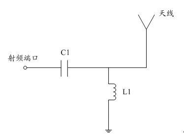
[0026] Wherein, the antenna matching circuit 13 includes: an adjustable capacitor C1 connected in series between the radio frequency port and the antenna 12, and a parallel inductor L1. The capacitance value of the adjustable capacitor C1 is controlled by the voltage control signal sent by the baseband unit 11 of the mobile phone.

[0027] In order to ensure that the antenna matching circuit 13 can optimally match the current network frequency band, the optimal antenna matching circuit parameters required by each network frequency band can be preset in the baseband unit 11 of the mobile phone. For example, when the mobile phone detects that the current network is in the GSM900 frequency band, the baseband unit 11 of the mobile phone automatically calls the...

Embodiment 2

[0031] With the development of wireless mobile network technology, mobile phones need to support more and more network frequency bands. From the previous need to support 2~3 network frequency bands to now need to support 4~5 network frequency bands. In order to realize that the mobile phone supports multiple network frequency bands, and to ensure that the antenna matching circuit corresponding to each network frequency band can achieve optimal power matching, this embodiment adds a voltage control unit between the adjustable capacitor and the baseband unit of the mobile phone. The unit can be connected with multiple adjustable capacitors to realize that the antenna matching circuit can be built into an antenna matching circuit with multiple matching parameters.

[0032] Such as Figure 5 As shown, the mobile phone 20 provided in this embodiment includes: a mobile phone baseband unit 21 , an antenna 22 , an antenna matching circuit 23 connected to the antenna for power matching...


PUM


Abstract

The invention provides an adjustable mobile phone antenna matching circuit and a mobile phone using the same. The antenna matching circuit is characterized in that a capacitance is connected between an antenna and a radio frequency port in series, and an inductance is connected between the antenna and the radio frequency port in parallel; and the capacitance is an adjustable capacitance, and the capacitance value thereof is controlled by a voltage control signal sent by a mobile phone baseband unit. The mobile phone comprises the mobile phone baseband unit, the antenna and the antenna matching circuit which is connected with the antenna and is used for realizing power matching; and the capacitance in the antenna matching circuit is the adjustable capacitance, and the capacitance value thereof is controlled by the voltage control signal sent by the mobile phone baseband unit. The antenna matching circuit and the mobile phone ensure that the optimal matching of the mobile phone antenna and the mobile phone antenna matching circuit is realized under all network frequency ranges.

Description

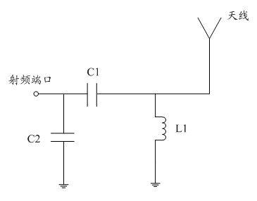
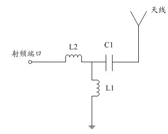
[0001] technical field [0002] The invention relates to the technical field of wireless mobile communication, in particular to an adjustable mobile phone antenna matching network circuit and a mobile phone using the circuit. Background technique [0003] With the development of wireless mobile network technology, mobile phones need to support more and more network frequency bands. From the previous need to support 2~3 network frequency bands to now need to support 4~5 network frequency bands. However, the current mobile phone has a fixed antenna matching circuit structure, that is, a group of antenna matching circuits needs to cooperate with all mobile phone frequency bands in the wireless mobile communication network. [0004] like figure 1 As shown, when the mobile phone antenna matching circuit topology is selected as L-type, that is, when a capacitor C1 is connected in series between the antenna and the RF port, and an inductor L1 is connected in parallel, no matter...

Claims


Application Information

Patent Timeline
IPC IPC(8): H04M1/02
Inventor 罗敏丽张莲
Owner HUIZHOU TCL MOBILE COMM CO LTD
Learn More