
Improved sludge mixing device

A technology of mixing equipment and sludge, applied in the direction of dewatering/drying/concentrating sludge treatment, etc., can solve the problems of large energy consumption of sludge conditioning tank, incomplete sludge flocculation, and unadjustable stirring speed, so as to save stirring equipment. , Reduce the moisture content of sludge, good mixing effect

Active Publication Date: 2012-09-19
BEIJING ENFI ENVIRONMENTAL PROTECTION CO LTD
View PDF0 Cites 0 Cited by
  • Summary
  • Abstract
  • Description
  • Claims
  • Application Information

AI Technical Summary

Problems solved by technology

[0004] Therefore, the traditional sludge conditioning tank consumes a lot of energy, and because the stirring speed cannot be adjusted, the flocculated sludge is easily broken again, so the sludge flocculation is not complete and the mixing effect is not good.

Method used


Image

  • Improved sludge mixing device
  • Improved sludge mixing device
  • Improved sludge mixing device

Examples


Embodiment Construction

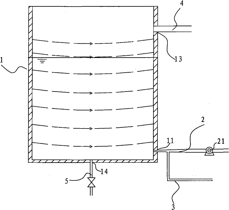
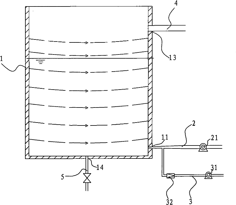
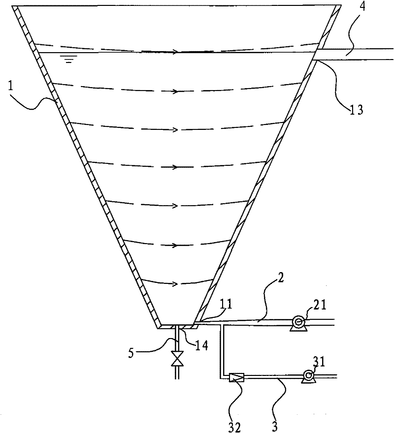
[0026] Embodiments of the present invention are described in detail below, examples of which are shown in the drawings, wherein the same or similar reference numerals designate the same or similar elements or elements having the same or similar functions throughout. The embodiments described below by referring to the figures are exemplary only for explaining the present invention and should not be construed as limiting the present invention.

[0027] In the description of the present invention, the orientation or positional relationship indicated by the terms "inner", "outer", "upper", "lower", "top", "bottom" etc. are based on the orientation or positional relationship shown in the drawings, The disclosure is merely for convenience in describing the invention and does not require that the invention must be constructed and operated in a particular orientation, and thus should not be construed as limiting the invention.

[0028] Refer below Figure 1-Figure 3 A sludge mixing d...


PUM


Abstract

The invention discloses a sludge mixing device, which comprises a mixing vessel, a sludge feeding pipe, a chemical feed pipe and a sludge discharging pipe, wherein the position adjacent to the bottom of the mixing vessel on the side wall of the mixing vessel is provided with a sludge inlet, and the position adjacent to the top of the mixing vessel on the side wall of the mixing vessel is providedwith a sludge outlet; the sludge feeding pipe is connected with the sludge outlet and used for feeding the sludge to be treated into the mixing vessel; one end of the chemical feed pipe is communicated with parts of the sludge feeding pipe outside the mixing vessel and used for feeding chemicals into the sludge feeding pipe so as to deliver the chemicals to the mixing vessel by the sludge feedingpipe; and the sludge discharging pipe is connected with the sludge outlet and used for discharging the sludge. According to the sludge mixing device of the embodiment of the invention, under the action of negative pressures in the pipes, in the process of feeding the chemicals, the chemicals are delivered to the sludge feeding pipe by the chemical feed pipe, then the chemicals and the sludge are transmitted to the mixing vessel together to carry out a plurality of mixing, so that the mixing effect is preferable, and parts of energy consumption for transmitting the chemicals can be saved.

Description

technical field [0001] The invention relates to the field of sewage treatment, in particular to an improved sludge mixing equipment. Background technique [0002] In the field of sewage treatment, before dehydrating sludge, in order to improve the dehydration effect of sludge, it is necessary to add some chemicals to flocculate the sludge, so that the suspended matter in the sewage settles into sludge. The degree of mixing of chemicals and sludge will directly affect the effect of sludge flocculation and subsequent dehydration. [0003] The traditional sludge and chemical mixing equipment is a sludge conditioning tank, which is usually a square tank. The sludge and chemical enter the pool from the bottom of the pool, and the chemical is directly transported to the inside of the tank through a delivery pump, which consumes a lot of energy. Moreover, the mixing effect of the agent and the sludge is not very good. In addition, the mixing of medicament and sludge needs to be s...

Claims


Application Information

Patent Timeline
Patent Type & Authority Patents(China)
IPC IPC(8): C02F11/14
Inventor 潘志平卢东昱魏巍孔荟马孝贤
Owner BEIJING ENFI ENVIRONMENTAL PROTECTION CO LTD
Learn More