Energy-saving cast-in-place hollow floor

A hollow floor and cast-in-place technology, which is applied to the preparation of floors and building components on site, and structural elements, etc., can solve the problems of simultaneous construction of floor heating devices, increased building development and construction costs, and unbalanced force transmission, etc. problem, achieve the effect of improving the anti-seismic cracking effect, light weight, and preventing concrete cracking

Inactive Publication Date: 2011-04-06
王本淼
View PDF4 Cites 21 Cited by
  • Summary
  • Abstract
  • Description
  • Claims
  • Application Information

AI Technical Summary

Problems solved by technology

[0002] Most of the conventional large-span building structure systems use cast-in-place hollow floors, and hollow tubes or thin-walled boxes are used to solve the technical problem of non-centering holes, but the hollow tubes or thin-walled boxes are permanently buried in the floor. It can only play the role of non-centering hole forming. Although the foundation load of the floor is large and the shockproof performance is good, the construction cost is high.
In addition, in order to achieve the purpose of central heating, after the pouring of the floor is completed, the second installation of the floor heating device must be carried out on the building, which increases the development and construction costs of the building, and at the same time fails to achieve the energy-saving and land-saving model advocated by the state. Requirements for low-carbon and environmentally friendly building structures
[0003] In the invention patent of his early patent ZL02282007, the applicant disclosed a thin-walled box for fasting floors, using this component to successfully solve the technical problem of non-core-pulling holes for cast-in-place fasting floors, and at the same time It solves the defect of unbalanced force transmission in the vertical and horizontal directions of the floor in the prior art, which can greatly reduce the weight of the foundation load, enhance the earthquake resistance, reduce the cost, and realize the arbitrary partition of the building space. This technology is now widely used in the construction industry
[0004] However, the hollow floor built with such a thin-walled box still needs to be installed twice after the floor is poured, which cannot satisfy the simultaneous construction of the floor and the building heating to achieve the goal of low carbon and energy saving. socioeconomic effect

Method used


Image

  • Energy-saving cast-in-place hollow floor
  • Energy-saving cast-in-place hollow floor
  • Energy-saving cast-in-place hollow floor

Examples


Embodiment Construction

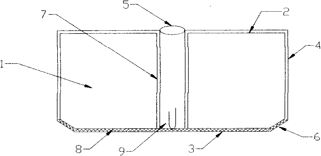
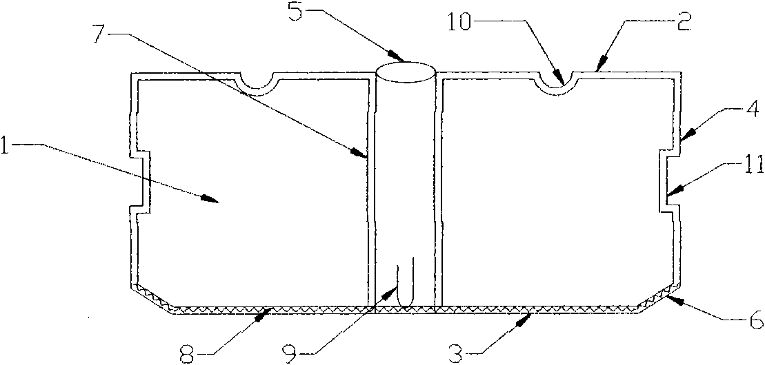
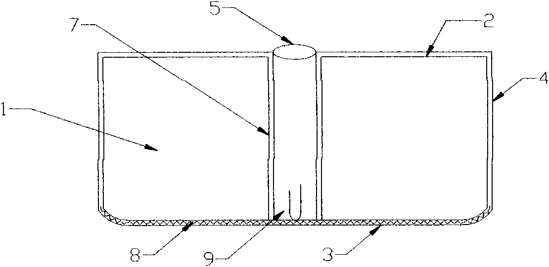
[0029] The present invention will be further described now in conjunction with accompanying drawing, as Figure 1a As shown, the thin-walled box body 1 used in the energy-saving cast-in-place hollow floor of this scheme is composed of bottom surface 3, side surface 4, top surface 2, inclined surface 6 and hole wall 7, and is formed by combining the bottom surface formwork, side formwork and inclined surface formwork. The finished one-time molding mold is applied to the inner wall of the mold with cement mortar to form the bottom surface 3, the side surface 4 and the inclined surface 6 of the thin-walled box body 1. In order to enhance the strength of the thin-walled box, reinforcing materials can be added to the cement mortar. The reinforcing materials can be steel wire mesh, glass fiber cloth, short fiber wire, short iron wire, etc. Preferably, steel wire mesh 8 is used as reinforcing material on the bottom surface 3 and inclined surface 6 of the thin-walled box body, and iron...


PUM


Abstract

The invention relates to an energy-saving cast-in-place hollow floor, which comprises thin-wall box bodies, a rib beam between the box bodies and an upper flange plate, wherein the upper flange plate contains an electric heating tube, and an electric heater and heat retention liquid are arranged in the electric heating tube; the top surface of the thin-wall box body is provided with at least one groove, the lateral surface of the thin-wall box body is provided with a closed hole, the closed holes of the adjacent box bodies are connected through a junction pipe, the lower end of the hole wall is connected with the bottom surface and closed, and the upper end of the hole wall is communicated with the top surface to form a hole; and the inclined plane and the bottom surface of the box bodies form an included angle of 100 to 165 degrees, and the side length of the inclined plane is more than 20 millimeters. Sunken closed holes are reserved on the lateral surfaces of the box bodies, the closed holes are opened before casting and the junction pipe can pass through the open closed holes to form an interconnected through heat energy blowing passage, and grooves for laying heating pipes are reserved on the top surfaces of the thin-wall box bodies to form a floor energy supply system. The floor adopting the thin-wall box bodies has the advantages of light weight, high hardness, reasonable structure, energy conservation, environment friendliness, cracking resistance and seismic resistance, and also can solve the heating problem by using the box bodies to transfer the heat energy.

Description

technical field [0001] The invention relates to a construction equipment, in particular to an energy-saving cast-in-place hollow floor. Background technique [0002] Most of the conventional large-span building structure systems use cast-in-place hollow floors, and hollow tubes or thin-walled boxes are used to solve the technical problem of non-centering holes, but the hollow tubes or thin-walled boxes are permanently buried in the floor. It can only play the role of non-centering hole forming. Although the foundation load of the floor is large and the shockproof performance is good, the construction cost is high. In addition, in order to achieve the purpose of central heating, after the pouring of the floor is completed, the second installation of the floor heating device must be carried out on the building, which increases the development and construction costs of the building, and at the same time fails to achieve the energy-saving and land-saving model advocated by the s...

Claims


Application Information

Patent Timeline
Patent Type & Authority Applications(China)
IPC IPC(8): E04B5/36E04B5/48E04G15/06E04C5/01E04C5/07
Inventor 王本淼王海崴
Owner 王本淼
Why Eureka
Try Eureka