Working sealing device for water turbine spindle

A technology for sealing devices and water turbines, which is applied in engine sealing, hydroelectric power generation, mechanical equipment, etc. It can solve the problems of no self-compensation, fast wear of the contact surface of the sealing block, etc., and achieve lower bearing height, good sealing performance, and reduced maintenance The effect of times

Active Publication Date: 2013-03-13
LANZHOU ELECTRIC CORP
View PDF0 Cites 0 Cited by
  • Summary
  • Abstract
  • Description
  • Claims
  • Application Information

AI Technical Summary

Problems solved by technology

[0003] In addition, there is also a structure in which the working seal of the main shaft of the turbine is arranged outside the bearing. The seal block is an L-shaped seal block that is in close contact with the periphery of the rotating oil basin. The contact surface of the seal block wears quickly and has no self-compensation function.

Method used


Image

  • Working sealing device for water turbine spindle
  • Working sealing device for water turbine spindle
  • Working sealing device for water turbine spindle

Examples


Embodiment Construction

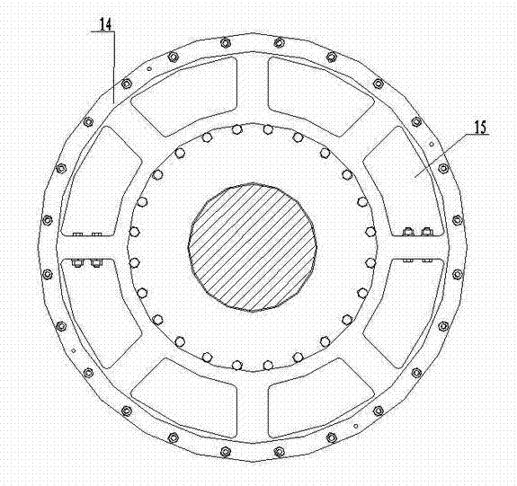
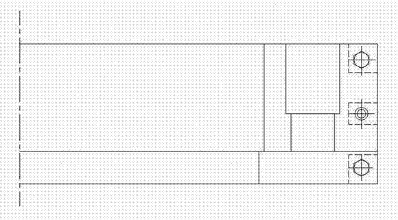
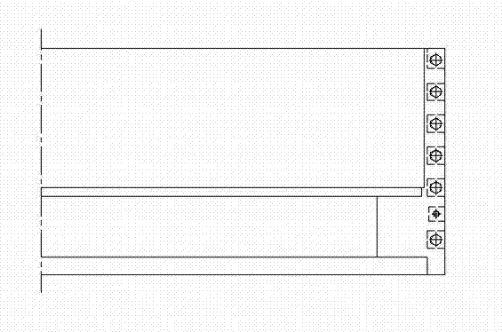
[0015] Such as Figure 1 to Figure 4 As shown, in the embodiment of the hydraulic turbine main shaft working sealing device provided by the present invention, it includes a sealing block 2, a sealing block 2 and an anti-wear ring 1, a sealing box 5, a decompression drain pipe 7, a sealing cover 8 and an air shroud 10 Together they form a sealing mechanism, the sealing block 2 below the anti-wear ring 1 is sleeved on the upper end of the positioning screw 3 in the sealing box 5, the lower end of the positioning screw 3 is fixed on the bottom of the sealing box 5, the pressure water inlet pipe 4 and the bottom of the sealing block 2 The cavity of the sealing box 5 is connected, and the anti-wear ring 1 and the sealing block 2 below are in close contact and fit under the action of the water inlet pressure of the pressure inlet pipe 4. The sealing box 5 is installed above the sealing cover 8, and the decompression drain pipe 7 is connected to the sealing cover. The labyrinth groov...


PUM


Abstract

The invention discloses a working sealing device for a water turbine spindle. A sealing mechanism consists of a sealing block, a wear-resistant ring, a sealing box, a decompression drain pipe, a sealing cover and an air shroud; the sealing block below the wear-resistant ring is sleeved at the upper end of a positioning screw in the sealing box; the lower end of the positioning screw is fixed at the bottom of the sealing box; a pressure water inlet pipe is communicated with the cavity of the sealing box at the bottom of the sealing block; the wear-resistant ring is in close contact fit with the sealing block below the wear-resistant ring under the action of water inlet pressure of the pressure water inlet pipe; the sealing box is arranged above the sealing cover; the decompression drain pipe is communicated with a drain hole of a labyrinth slot in the sealing cover; the sealing cover is arranged on a top cover of a water guide mechanism; and the air shroud is arranged between the sealing cover and the top cover. The sealing mechanism is arranged outside a rotation oil pan of the spindle, wherein the wear-resistant ring is fixedly connected with the periphery of the rotation oil pan. The sealing device has the self compensating function, reduces overhauling times, prolongs the service life, has high sealing performance, and improves the running stability of a water turbine.

Description

technical field [0001] The invention relates to a sealing device of a water turbine, in particular to a working sealing device of a main shaft of the water turbine. Background technique [0002] A small amount of water leakage will occur in the anti-leakage ring of the runner of the water turbine during operation, and the water leakage will enter the machine pit along the gap between the main shaft of the water turbine and the fixed parts, making the water turbine unable to operate normally. The technical measures taken to solve this problem in the prior art are generally to install a working sealing device under the main shaft bearing of the turbine. The working sealing device needs to be replaced frequently because the sealing block and the anti-wear ring are easy to wear. When the sealing block and the anti-wear ring are worn out for maintenance and replacement, it is necessary to dismantle the floor of the turbine floor, bearings, and disassemble the water guiding mechan...

Claims


Application Information

Patent Timeline
Patent Type & Authority Patents(China)
IPC IPC(8): F03B11/00F16J15/46F16J15/54
CPCY02E10/226Y02E10/20
Inventor 嵇月明魏本斐李生军王长娃
Owner LANZHOU ELECTRIC CORP
Why Eureka
Try Eureka