High-power light-emitting diode (LED) lamp

An LED lamp, high-power technology, applied in the field of electric light source, can solve the problem of aluminum plate heat energy not being able to transfer quickly, and achieve the effect of reducing temperature

Inactive Publication Date: 2011-04-06
张春华
View PDF3 Cites 2 Cited by
  • Summary
  • Abstract
  • Description
  • Claims
  • Application Information

AI Technical Summary

Problems solved by technology

[0002] Existing high-power LED lamps all need to be provided with a heat sink, and the better the heat dissipation effect, the higher the power of the LED lamp. The back of the aluminum plate where the lamp beads are fixed, the heat transfer from the lamp beads to the back of

Method used


Image

  • High-power light-emitting diode (LED) lamp
  • High-power light-emitting diode (LED) lamp
  • High-power light-emitting diode (LED) lamp

Examples


Embodiment 1

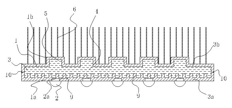
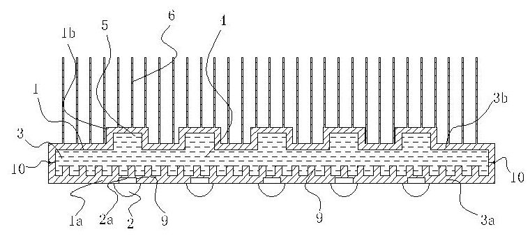
[0011] Embodiment 1: as figure 1 As shown, the present invention includes a heat dissipation plate 1, a heat dissipation surface 2a fixed on the front 1a of the heat dissipation plate 1 unit LED lamp 2, and its special feature is that the heat dissipation plate 1 is provided with an airtight cavity 3, and the airtight cavity 3 is provided with a high-efficiency The thermal energy transfer liquid 4 is provided with several grooves 5 on the side of the closed cavity 3 away from the unit LED lamp 2 . In order to speed up the heat dissipation speed of the unit LED lamp 2 to the heat dissipation plate 1 , the heat dissipation surface 2 a of the unit LED lamp 2 is embedded in the inlay groove 9 of the heat dissipation plate 1 . Radiation fins 6 are provided on the back surface 1b of the heat dissipation plate 1 . Several sheet-shaped protrusions 9 are provided on the side close to the unit LED lamp 2 in the closed cavity 3 to increase the heating area of ​​the high-efficiency h...

Embodiment 2

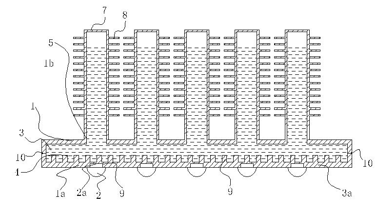
[0012] Embodiment 2: as figure 2 As shown, the present invention includes a heat dissipation plate 1, a heat dissipation surface 2a fixed on the front 1a of the heat dissipation plate 1 unit LED lamp 2, and its special feature is that the heat dissipation plate 1 is provided with an airtight cavity 3, and the airtight cavity 3 is provided with a high-efficiency The thermal energy transfer liquid 4 is provided with several grooves 5 on the side of the closed cavity 3 away from the unit LED lamp 2 . Several heat pipes 7 are arranged on the back side 1 b of the heat dissipation plate 1 , and the heat pipes 7 communicate with the grooves 5 on the inner cavity 3 of the heat dissipation plate 1 . Several cooling fins 8 are arranged on the heat pipe 7 .


PUM


Abstract

The invention relates to a high-power light-emitting diode (LED) lamp. The high-power LED lamp comprises a radiating plate, and a unit LED lamp of which the radiating surface is fixed in front of the radiating plate. The high-power LED lamp is characterized in that: a closed accommodating cavity is formed in the radiating plate; high-efficiency heat energy transfer liquid is filled in the closed accommodating cavity; and the side, which is far away from the unit LED lamp, in the closed accommodating cavity is provided with a plurality of grooves. Compared with the prior art, the high-power LED lamp has the advantage that: the heat of an aluminum plate fixedly connected with an LED lamp bead can quickly flow away, so that the temperature of the LED lamp bead is effectively and quickly reduced.

Description

technical field [0001] The invention relates to an electric light source. Background technique [0002] Existing high-power LED lamps all need to be provided with a heat sink, and the better the heat dissipation effect, the higher the power of the LED lamp. The back of the aluminum plate where the lamp beads are fixed, the heat transfer from the lamp beads to the back of the aluminum plate can only rely on the aluminum plate itself, limited by the structure of the heat pipe itself, the heat pipe can only contact a small part of the back of the aluminum plate, so that the heat on the aluminum plate Can not be quickly transferred to the heat pipe. Contents of the invention [0003] The object of the present invention is to provide a high-power LED lamp in which the heat energy of the aluminum plate fixedly connected with the LED lamp bead can flow away quickly, thereby effectively and rapidly reducing the temperature of the LED lamp bead. [0004] The present invention...

Claims


Application Information

Patent Timeline
IPC IPC(8): F21S2/00F21V29/00F21V17/00F21V19/00F21Y101/02F21V29/51F21V29/74
Inventor 张春华
Owner 张春华
Why Eureka
Try Eureka