Dye sensitized solar cell and preparation method thereof

A solar cell and dye sensitization technology, applied in the field of solar cells and their preparation, can solve problems affecting installation, use, and hindering the industrialization of DSC, and achieve the effects of reducing self-weight, reducing the risk of short circuit, and reducing costs

Inactive Publication Date: 2011-04-06
EAST CHINA NORMAL UNIV +1
View PDF5 Cites 24 Cited by
  • Summary
  • Abstract
  • Description
  • Claims
  • Application Information

AI Technical Summary

Problems solved by technology

This is mainly due to the fact that the expensive transparent conductive substrate in the raw material accounts for a considerable proportion of the cost, on the other hand, the transparent conductive substrate used in the battery is usually FTO conductive glass, which makes the weight of the battery another problem , affecting its installation, use, etc., hindering the industrialization of DSC

Method used


Image

  • Dye sensitized solar cell and preparation method thereof
  • Dye sensitized solar cell and preparation method thereof
  • Dye sensitized solar cell and preparation method thereof

Examples


Embodiment 1

[0029] Example 1, liquid single substrate dye-sensitized solar cell

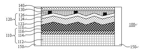
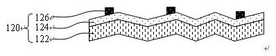
[0030] figure 1 is a schematic cross-sectional structure diagram of a liquid single-substrate dye-sensitized solar cell 100 . refer to figure 1 , the liquid single-substrate dye-sensitized solar cell 100 includes a photoanode 110 , a counter electrode 120 , a liquid electrolyte 130 , and an encapsulation shell. The photoanode 110, the counter electrode 120 and the liquid electrolyte 130 are all packaged in the encapsulation shell. The encapsulation shell includes a cover glass 140 and an encapsulation material 150 , wherein the cover glass 140 is placed on the counter electrode 120 , and the encapsulation material 150 encapsulates the photoanode 110 and the counter electrode 120 in its entirety.

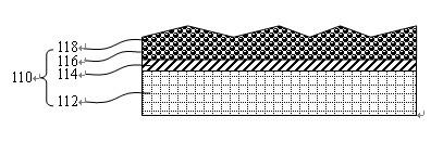
[0031] refer to figure 2 , the photoanode 110 includes a transparent conductive substrate 112, a transparent conductive film 114 deposited on the surface of the transparent conductive substrate 112, and a poro...

Embodiment 2

[0045] Example 2, quasi-solid-state single-substrate dye-sensitized solar cell

[0046] Figure 5 is a schematic cross-sectional structure diagram of a quasi-solid-state single-substrate dye-sensitized solar cell 200 . The same content as in Example 1 will not be repeated here. The quasi-solid single-substrate dye-sensitized solar cell 200 is composed of a photoanode 110 , a counter electrode 120 , a quasi-solid electrolyte 230 , and an encapsulation shell 150 .

[0047] refer to Figure 5 and Figure 8 , the quasi-solid electrolyte 230 shown in the figure actually does not just exist above the counter electrode 120, but completely wets the entire counter electrode 120, and completely fills the entire space between the photoanode 110 and the encapsulation material 150. space.

[0048] The quasi-solid electrolyte 230 is a quasi-solid redox electrolyte. In this embodiment, the preferred composition of the quasi-solid electrolyte 230 is 0.6M 1-propyl-3 methylimidazolium iodi...


PUM

PropertyMeasurementUnit
thicknessaaaaaaaaaa
thicknessaaaaaaaaaa
thicknessaaaaaaaaaa

Abstract

The invention discloses a dye sensitized solar cell, which comprises an optical anode, a counter electrode, electrolyte and a packaging shell. The counter electrode is positioned above the optical anode and is arranged inside the packaging shell; the electrolyte is full of the packaging shell; the optical anode comprises a transparent conductive substrate, a transparent conductive film and a porous transition metal oxide film which adsorbs dye molecules; the porous transition metal oxide film is coated on the transparent conductive film; and the counter electrode comprises a diaphragm serving as a substrate of the counter electrode, and a catalytic material and a grid electrode which are deposited on the diaphragm in turn. The invention also discloses a method for preparing the dye sensitized solar cell. The invention reduces the manufacturing cost, lightens the cell weight, reduces the short circuit risk and shortens the electronic transmission distance, and the dye sensitized solar cell is high-efficiency.

Description

technical field [0001] The invention relates to a solar cell and a preparation method thereof, in particular to a structural design, preparation and packaging method of a novel dye-sensitized solar cell. Background technique [0002] Nanocrystalline dye-sensitized solar cell (DSC) is a semiconductor optoelectronic device that directly converts solar energy into electrical energy based on the principle of photovoltaics, using a dye-sensitized porous nanostructured film as a photoanode. It is developed along with the development of semiconductor electrochemistry. A new field of scientific research. In 1991, the research team led by Professor Grötzel of the Lausanne Institute of Technology, Switzerland, used nano-TiO with a high specific surface area 2 The porous film is used as the semiconductor electrode, and the organometallic compound such as Ru is used as the photosensitizing dye, and the appropriate redox electrolyte is selected as the medium to assemble TiO 2 Nanocryst...

Claims


Application Information

Patent Timeline
Patent Type & Authority Applications(China)
IPC IPC(8): H01G9/02H01G9/04H01G9/20H01M14/00H01L51/42H01L51/48
CPCY02E10/542Y02E10/549Y02P70/50
Inventor 黄素梅张丁文李晓冬尹希江
Owner EAST CHINA NORMAL UNIV
Why Eureka
Try Eureka