Back spot facing machining cutter and application method thereof

An application method and hole processing technology, applied in the direction of manufacturing tools, metal processing equipment, cutting tools for lathes, etc., can solve the problems of high price, complex structure, high cost, etc., and achieve the effect of improving processing efficiency and ingenious structure

Inactive Publication Date: 2011-04-13
CHINA XD ELECTRIC CO LTD
View PDF3 Cites 4 Cited by
  • Summary
  • Abstract
  • Description
  • Claims
  • Application Information

AI Technical Summary

Problems solved by technology

[0005] Backsinking knives produced by several foreign tool manufacturers do not require manual loading and unloading of the knives, but the structure is very complicated. The tool is equipped with a device similar to a clutch, which can automatically open and retract the blade, but the price is expensive and the cost is too high

Method used


Image

  • Back spot facing machining cutter and application method thereof
  • Back spot facing machining cutter and application method thereof
  • Back spot facing machining cutter and application method thereof

Examples


Embodiment Construction

[0022] The present invention is described in further detail below in conjunction with accompanying drawing:

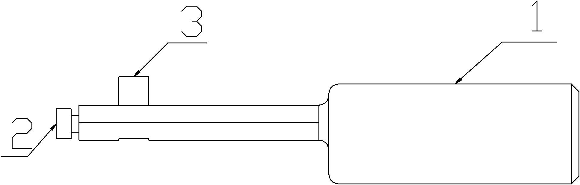
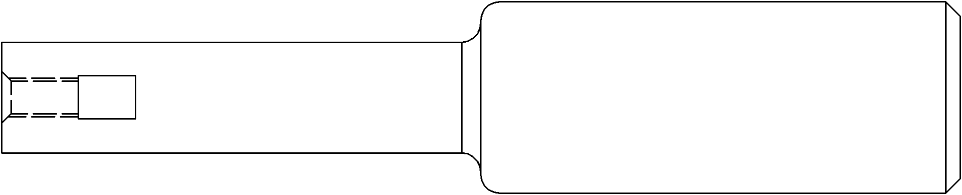
[0023] see figure 2 , a kind of countersinking processing tool, comprising a tool bar and a tool head, the front part of the tool bar is provided with a tool head mounting hole, and a tool head is fixedly installed in the tool head mounting hole; the front end of the tool bar is provided with a threaded through hole , a screw is installed on the through hole; the screw is fixedly connected with the cutter head.

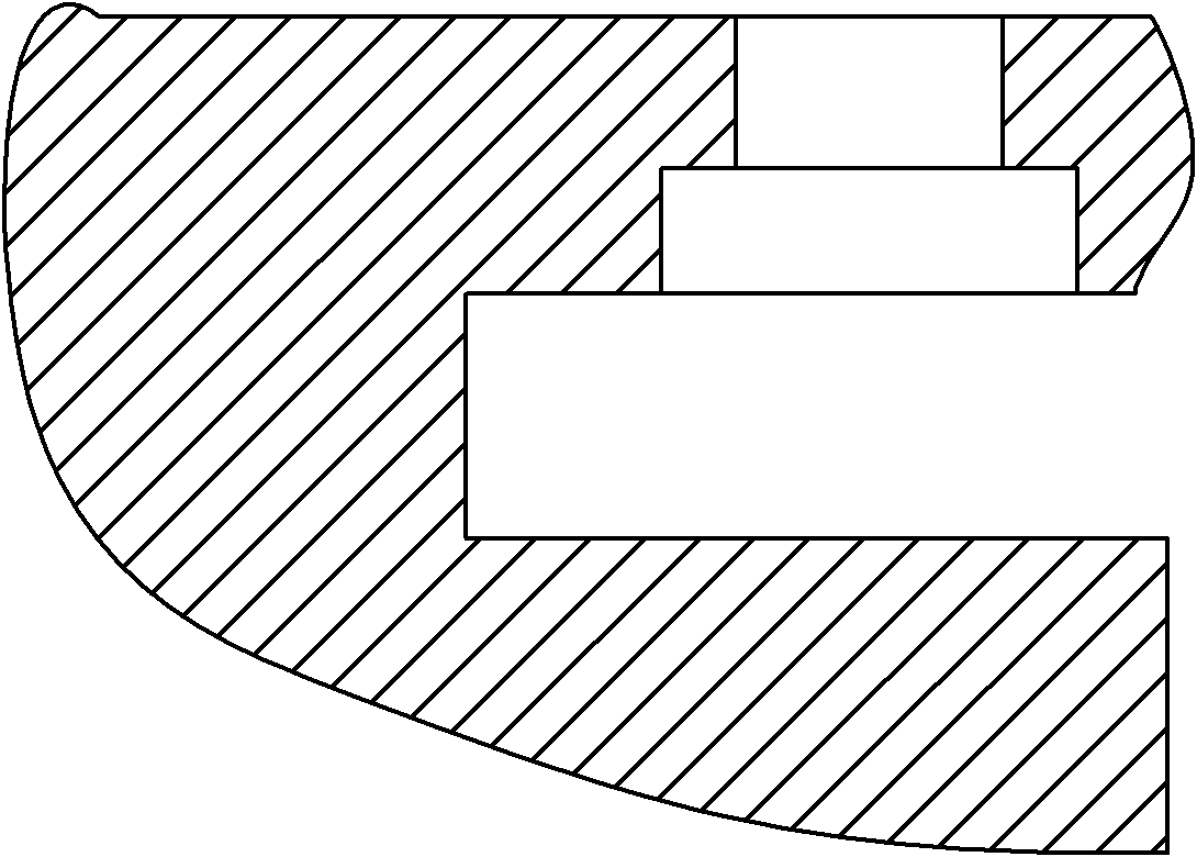
[0024] The upper part of the tool bar is the clamping part of the tool handle, with a circular cross section, and the lower part is the contact part with the parts during processing. The cross section is formed by two identical circular arcs facing each other; front face.

[0025] see Figure 4 , There are two φ13 arcs on the "Jujube core"-shaped tool bar, the center of one φ13 arc coincides with the center of the φ20 and φ14 holes in the clamping part of ...


PUM


Abstract

The invention discloses a back spot facing machining cutter and an application method thereof. The cutter comprises a cutter bar, a cutter head and a bolt, wherein a cutter head mounting hole is formed on the front part of the cutter bar, and the cutter head is fixed in the cutter head mounting hole; a threaded through hole is formed at the front end of the cutter bar, and the bolt is arranged in the through hole; and the bolt is fixedly connected with the cutter head. The back spot facing machining cutter has the advantages that: the problems of manual cutter assembly and disassembly, shut down and low machining efficiency during the traditional machining process of back spot facing can be solved by designing the special back spot facing machining cutter which has a smart manufacturing structure and is simple and practical, and automatic machining process of the back spot facing is realized; a special cutter is provided for the equipment with high machining automation degree, such as horizontal machining equipment, vertical machining equipment and the like, a mechanical arm can automatically change a cutter, and the machining efficiency can be greatly improved.

Description

Technical field: [0001] The invention belongs to the field of tool processing, and relates to a countersink machining tool and an application method thereof, in particular to a special machining tool for countersinking on high-voltage switchgear parts and an application method thereof. Background technique: [0002] In the prior art, when processing the back spot facing, the tool is fed from the end face of the large hole, and the small hole is processed first, and then the large hole is processed. However, due to the limitation of the structure of some parts, the tool is fed from the end face of the large hole, and the tool and the part will interfere, so the tool can only be fed from the end face of the small hole. Bottom of the large hole to the direction of the small hole) to process the large hole. This kind of large hole is called "back countersinking", this processing method is called "backsinking processing", and the tool used is called "backsinking knife". figure ...

Claims


Application Information

Patent Timeline
Patent Type & Authority Applications(China)
IPC IPC(8): B23B27/00
Inventor 马敏陈继霞
Owner CHINA XD ELECTRIC CO LTD
Why Eureka
Try Eureka