Float glass melting furnace

A technology of float glass and melting furnace, which is applied in the field of float glass melting furnace, which can solve the problems of easy material leakage at the bottom of the pool, easy damage of bricks at the bottom of the pool, easy blockage of the bubbler tube, etc., to prolong the residence time and improve the melting quality Effect

Inactive Publication Date: 2011-04-13
ZHANGZHOU KIBING GLASS +1
View PDF1 Cites 5 Cited by
  • Summary
  • Abstract
  • Description
  • Claims
  • Application Information

AI Technical Summary

Problems solved by technology

However, the bubbling at the bottom of the pool is easy to damage the bricks at the bottom of the pool, the material at the bottom of the pool is easy to leak, or the bubbling tube is easy to block, which limits its application.
As ...

Method used


Image

  • Float glass melting furnace
  • Float glass melting furnace
  • Float glass melting furnace

Examples


Embodiment 1

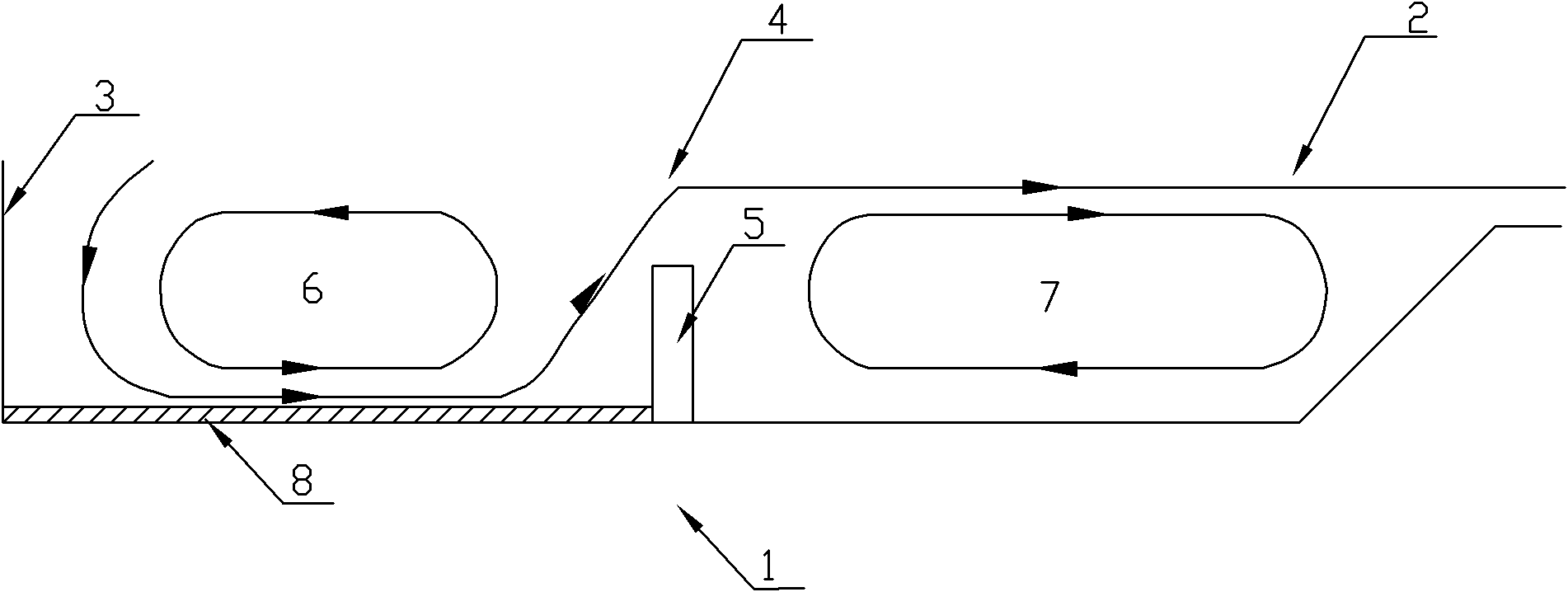
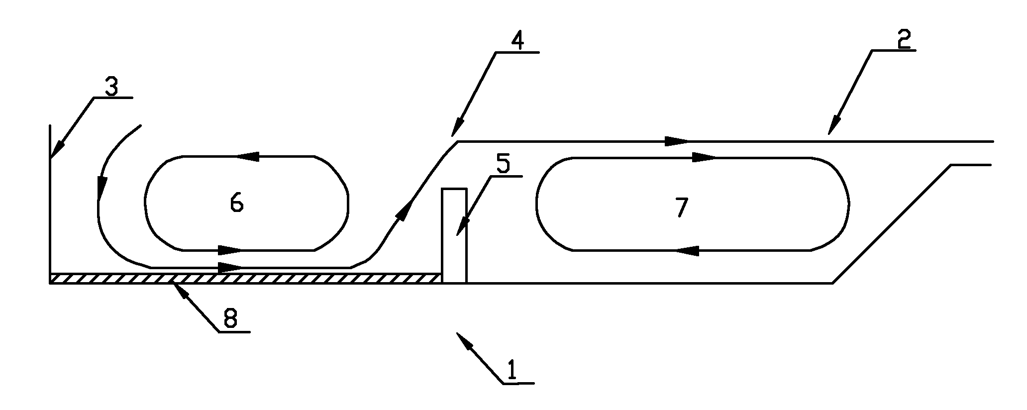
[0017] Example 1, please refer to figure 1 As shown, a float glass melting furnace of the present invention includes a melting part 1 arranged at the front section of the melting furnace; a feeding port 3 is provided at the front end of the melting part 1; a hot spot is arranged in the middle of the melting part 1 along the length direction 4. A kiln sill 5 is provided at the hot spot 4 of the melting part 1 to prevent the molten glass from flowing directly from the feeding port 3 to the cooling part 2 in the rear section of the melting furnace, so as to keep the circulation of the glass liquid on both sides of the hot spot stable; the kiln sill 5 The length dimension of the kiln is set to be the same as the width of the pool of the melting section 1; the height of the kiln sill 5 is set to 50% to 75% of the depth of the pool of the melting section 1; the thickness of the kiln sill 5 is set to 300 mm to 400 mm mm.

[0018] in,

[0019] The kiln ridge 5 is made of fused zirco...

Embodiment 2

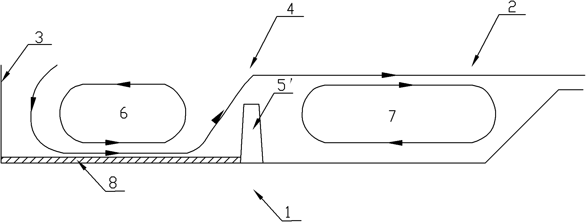
[0022] Example 2, please refer to figure 2 As shown, a float glass melting furnace of the present invention differs from the first embodiment above in that: the cross-sectional shape of the kiln ridge 5' is set as an isosceles trapezoid; and the height of the isosceles trapezoid is set as The height of the kiln ridge 5' and the kiln ridge 5' of this isosceles trapezoidal cross-section make the retaining wall of the kiln ridge 5' a slope structure. The trapezoidal kiln sill 5' can also maintain the stability of the first circulating glass liquid flow 6 and the second circulating glass liquid flow 7 in the melting furnace, and prolong the residence time of the glass liquid in the melting part 1, thereby facilitating the flow of the glass liquid. clarification and homogenization; it can prevent the bottom dirt 8 of the melting part 1 from flowing directly to the cooling part 2, and part of the molten glass in the cooling part 2 flows back into the melting part 1 to be reheated, ...


PUM


Abstract

The invention discloses a float glass melting furnace, comprising a melting region which is arranged at the forepart of the melting furnace, wherein a charging opening is arranged at the front end of the melting region; a hot spot is arranged in the middle of the melting region along the length direction; a furnace bank is arranged at the hot spot of the melting region; the length dimension of the furnace bank is same as the width dimension of a pool of the melting region; the height of the furnace bank is 50-70% of the depth of the pool of the melting region; and the thickness of the furnace bank is 300-400mm. By adopting the structure, the float glass melting furnace can maintain the stability of two circulating glass melt flows in the melting furnace and prolong the residence time of the glass melt in the melting furnace to contribute to the clarification and the homogenization of the glass melt, and can prevent the dirty materials at the bottom of the pool of the melting region from directly flowing to a cooling region and prevent a part of the glass melt in the cooling region from reflowing to the melting region to be reheated, thereby improving the melting quality of the glass melt, saving the energy, and lowering the loss of the float glass melting furnace.

Description

technical field [0001] The invention relates to a float glass melting furnace, in particular to a float glass melting furnace which improves the structure of the melting part. Background technique [0002] Float glass is currently the main production process for flat glass, and the melting furnace is one of the most important thermal equipment in the float glass production process. For a long time, strengthening the scientific research on glass melting furnaces and improving the design level of glass melting furnaces has always been a subject of concern and attention to glass production researchers and designers. Improving the structure of the furnace can not only reduce the cost of glass production, but also improve the quality of glass. [0003] Glass melting is the process of adding batch materials into the melting furnace and heating at high temperature to form a uniform, bubble-free (that is, reduce bubbles, streaks and stones to the allowable level) glass liquid that ...

Claims


Application Information

Patent Timeline
IPC IPC(8): C03B18/16
Inventor 俞其兵邵景楚施敖荣官立民黄勇
Owner ZHANGZHOU KIBING GLASS
Why Eureka
Try Eureka