
Device and method for implementing local electroplating of parts

A technology for partial electroplating and parts, which is applied in the field of devices that can realize partial electroplating of parts, can solve problems such as affecting the assembly quality and service life of parts, unable to guarantee the uniformity of electroplating, and the coating layer is not bright and smooth enough, and achieves simple structure and good electrical conductivity. The effect of uniformity and current distribution

Inactive Publication Date: 2012-08-08
HUADONG PHOTOELECTRIC TECHN INST OF ANHUI PROVINCE
View PDF0 Cites 0 Cited by
  • Summary
  • Abstract
  • Description
  • Claims
  • Application Information

AI Technical Summary

Problems solved by technology

The above two electroplating methods not only seriously waste electroplating materials and production time, but also cannot accurately position the parts, cannot guarantee the uniformity of electroplating, and cannot guarantee the electroplating area, so that the integrity of the coating is easily damaged, resulting in spots, Roughness and unevenness of deposition and coating
In addition, especially when the blind hole of the part is partially electroplated, it is often found that there is a thick coating around the blind hole, while there is only a thin layer inside the blind hole, and the coating is not bright and flat enough. , affecting the assembly quality and service life of parts

Method used


Image

  • Device and method for implementing local electroplating of parts
  • Device and method for implementing local electroplating of parts
  • Device and method for implementing local electroplating of parts

Examples


Embodiment Construction

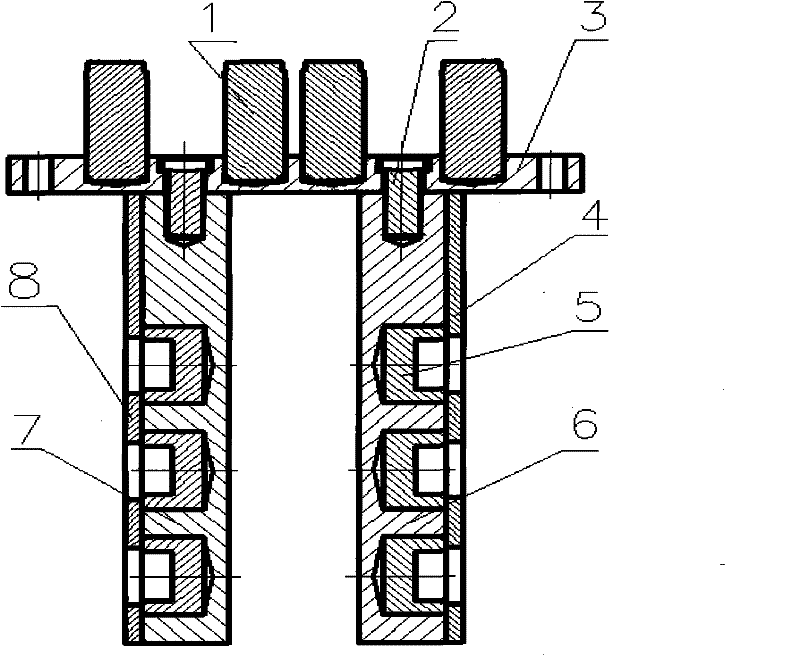
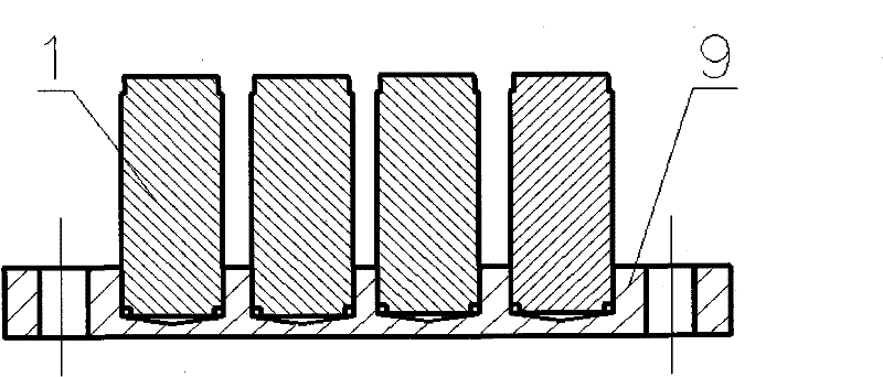
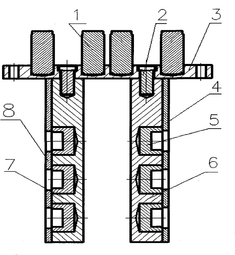
[0037] like figure 1 As shown, a partial electroplating device that can realize blind hole parts and non-blind hole parts at the same time, including copper base plates 3, 6, 7, copper cover plates 4, 8, screws 2, conductive rods (not shown), Wire (not shown) and metal plate (not shown), wherein the material of the metal plate is the material to be plated on the part. The copper bottom plates 3, 6, and 7 are circular, and there are grooves for matching parts on the copper bottom plates 3, 6, and 7, and there are a plurality of threaded openings (not shown in the figure) on the surrounding edges. The copper cover plates 4, 8 is also circular, and the through hole (figure not marked) that cooperates with parts is arranged on copper cover plate 4,8 and the threaded mouth that cooperates with the threaded mouth on copper base plate 3,6,7.

[0038] During electroplating, put blind hole parts 5 and non-blind hole parts 1 into the grooves of copper base plates 6, 7 and 3 respectivel...


PUM


Abstract

The invention discloses a device and a method for implementing local electroplating of parts. The device comprises a copper bottom plate, a copper cover plate, a conductive bar, screws, leads and a metal plate; when a blind hole part is locally electroplated, the non-electroplating part of the part is put into a groove of the copper bottom plate, then the copper cover plate is pressed on the metal plate, and the to-be-electroplated part of the part is naked outside the copper cover plate; when the local surface of a non blind hole part is electroplated, the non-electroplating part of the part is put into the groove of the copper bottom plate, and the to-be-electroplated surface is naked outside. The method comprises the following steps of: processing the copper bottom plate and the copper cover plate, chemically removing oil, coating a layer of vinyl perchloride varnish on the lower surface of the copper bottom plate and the upper surface of the copper cover plate respectively, airing the paint layers, fixing the part to be electroplated on the copper bottom plate, pressing the copper cover plate as required, then vertically hanging the whole assembly in the center of an electroplating bath, and switching on a power supply. The device has simple structure, is easy to process, accurately positions the plated surface of the part, saves the time and reduces the production cost.

Description

【Technical field】 [0001] The invention belongs to the technical field of surface treatment, in particular to a device and method capable of realizing partial electroplating of parts. 【Background technique】 [0002] At present, there are mainly two traditional ways to achieve partial electroplating of parts: one is to process the parts to be electroplated to a size 1-2mm larger than the actual requirement, then put them into a metal basket, and fix them on the conductive rods with copper wires. The overall electroplating is carried out first, and after the electroplating is completed, the end face of the part that does not need electroplating is processed to the required size. The second is to apply perchlorethylene varnish to the place where electroplating parts do not need to be electroplated. After the overall electroplating is completed with a metal basket, acetone is used to remove the perchlorethylene varnish. The above two electroplating methods not only seriously was...

Claims


Application Information

Patent Timeline
Patent Type & Authority Patents(China)
IPC IPC(8): C25D5/02
Inventor 吴华夏刘劲松胡海城张晓瑞何畔毕竞
Owner HUADONG PHOTOELECTRIC TECHN INST OF ANHUI PROVINCE
Learn More