Hydraulic excavator flow rate control method and control loop

A technology of flow control and circuit, which is applied in the direction of earth mover/shovel, mechanical equipment, servo meter circuit, etc., can solve the problems of reducing the service life of the motor, occupying the installation space of the whole machine, and increasing the system flow, so as to prolong the life of the motor. Longevity, reduced maintenance cost, and high operating efficiency

Inactive Publication Date: 2011-04-13
SANY HEAVY MACHINERY
View PDF4 Cites 43 Cited by
  • Summary
  • Abstract
  • Description
  • Claims
  • Application Information

AI Technical Summary

Problems solved by technology

However, on the one hand, the use of a pump with a large flow rate will increase the volume of the pump, occupy the limited installation space of the whole machine, and increase the cost; Flow, long-term use will damage the motor and reduce the service life of the motor

Method used


Image

  • Hydraulic excavator flow rate control method and control loop
  • Hydraulic excavator flow rate control method and control loop
  • Hydraulic excavator flow rate control method and control loop

Examples


Embodiment 1

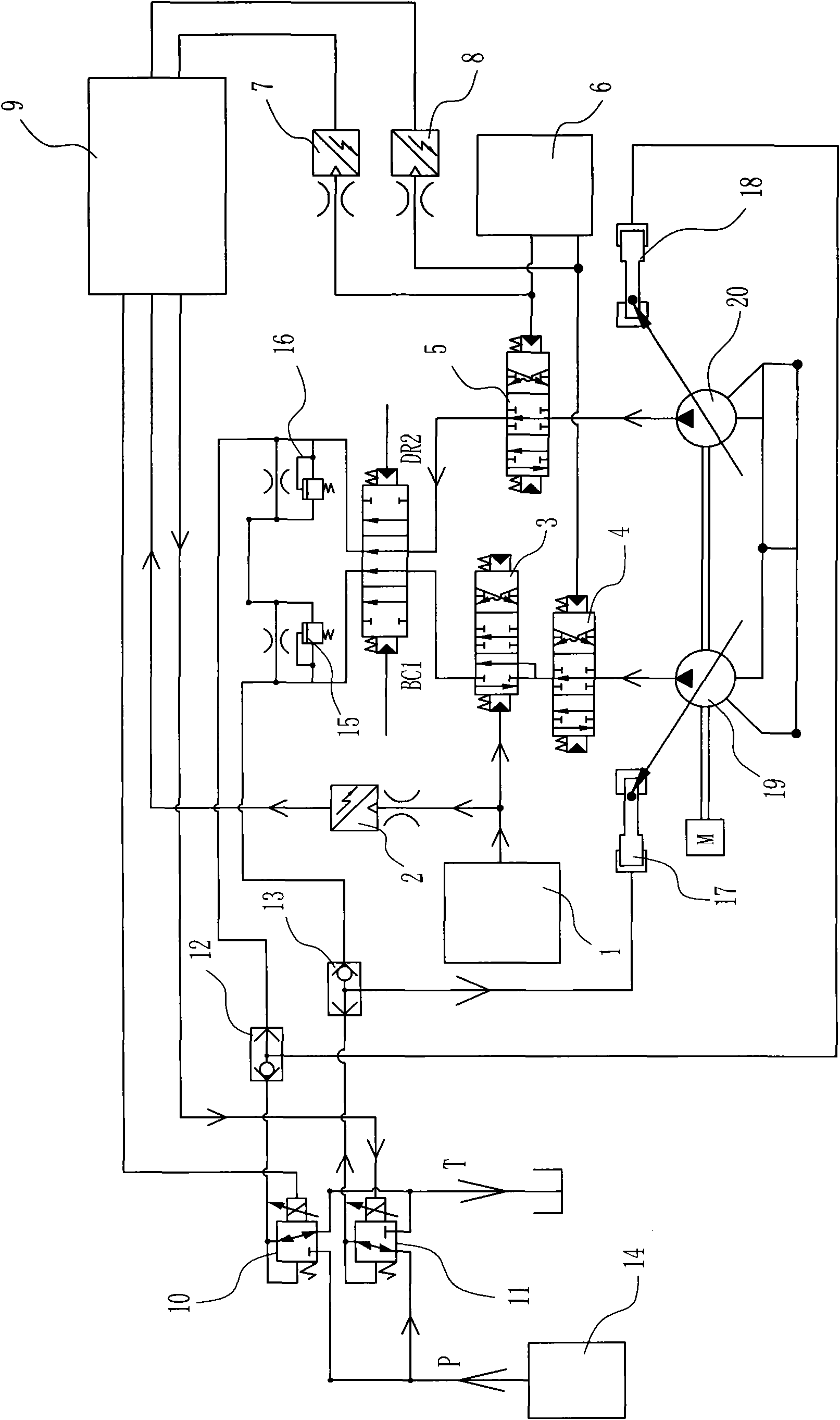
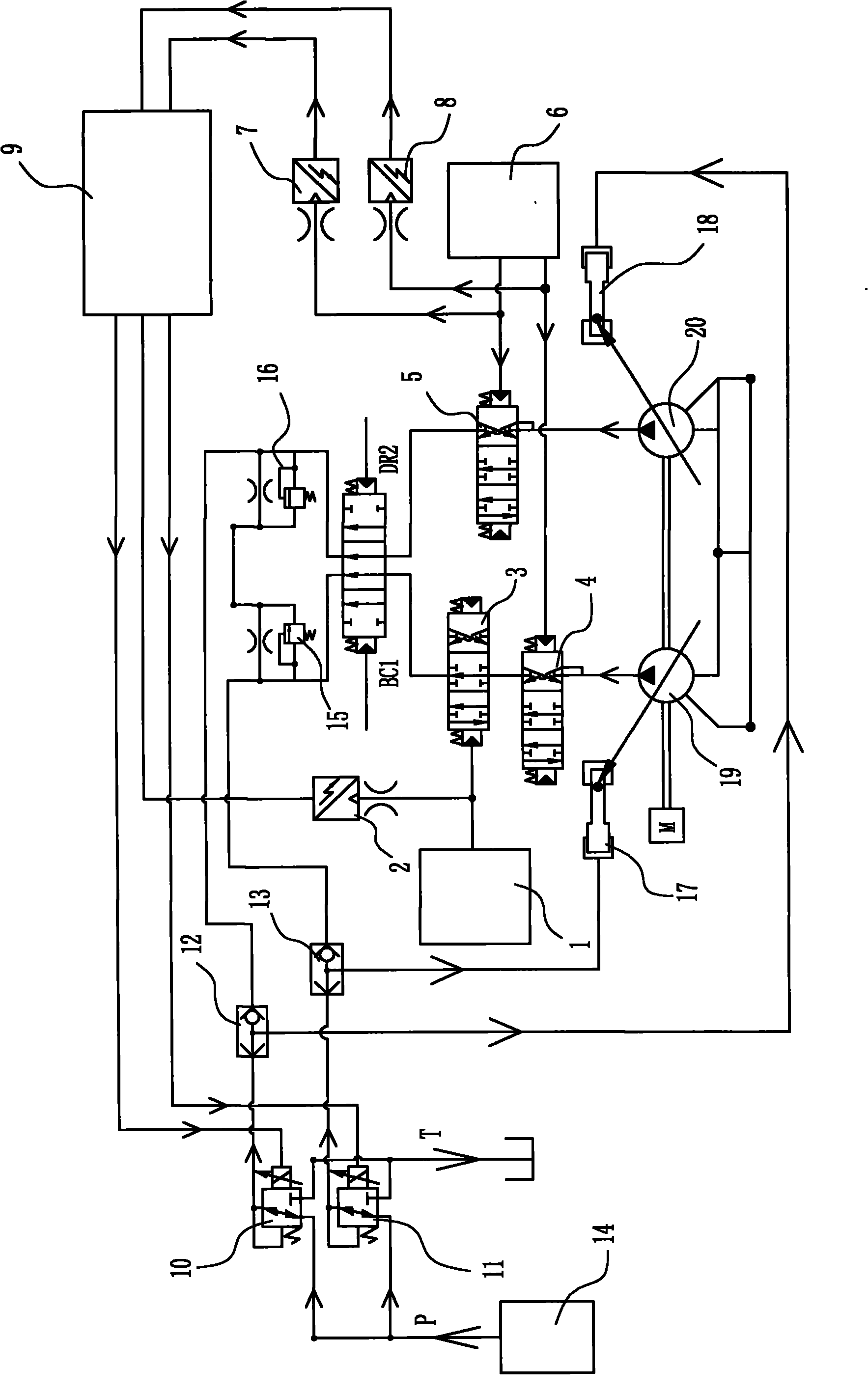
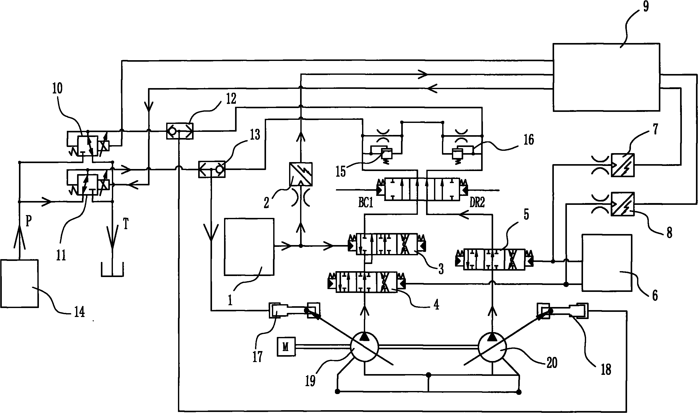
[0021] Embodiment one: see figure 1 , 2 As shown, a hydraulic excavator flow control circuit includes the first and second electromagnetic proportional valves and the first and second two OR-type three-way shuttle valves, the first and second electromagnetic proportional valves The input ends are respectively connected to the output port of the pilot gear 14 of the excavator, the output end of the first electromagnetic proportional valve 10 is connected to the P1 input port of the first or gate type three-way shuttle valve 12, and the second electromagnetic proportional valve 11 The output end is connected to the P1 input port of the second OR gate type three-way shuttle valve 13; the P2 input port of the first OR gate type three-way shuttle valve 12 is connected to the negative feedback spool 16 behind the excavator, and its A output port It is connected with the corresponding rear negative feedback regulator 18, the P2 input port of the second or gate type three-way shuttle...


PUM


Abstract

The invention discloses a hydraulic excavator flow rate control loop which comprises a hydraulic and electric control loop. The hydraulic excavator flow rate control loop is characterized by comprising two electromagnetic proportional valves and two or-gate type three-way shuttle valve, wherein the electric control ends of the proportional valves are respectively connected with the controller, the input end is connected with a pilot pressure pump of an excavator, the output end is connected with a input opening P1of one three-way shuttle valve, input openings P2 of the two three-way shuttle valves are respectively connected with a front negative feedback valve core and a back negative feedback valve of the excavator, and output openings A of the three-way shuttle valves are respectively connected with a front negative feedback regulator and a back negative feedback regulator. A method comprises the following steps of: receiving sensor signals by a controller; sending electromagnetic proportional valve electric control signals; opening proportional valve and shuttle valve paths; controlling the corresponding negative feedback regulators through the pressure of the proportional valves; and finally controlling the delivery capacity of the pump. The method realizes the limitation on the system delivery capacity through controlling the delivery capacity of the pump by using the electromagnetic proportional valves, so the flow rate maintains the normal state when a rotating or walking device works singly, and the damage to a motor caused by high flow rate is avoided.

Description

technical field [0001] The invention relates to an excavator control method, in particular to a hydraulic excavator flow control method and a control circuit. Background technique [0002] With the development of society and the needs of national construction, the scope of use of excavators is becoming wider and wider. Excavators play a pivotal role in mineral development, water conservancy construction and road construction. Efficiency and other aspects are more critical and put forward higher requirements. Especially due to the tight construction schedule, the customer requires the excavator to have higher operating efficiency and provide sufficient flow for various compound actions of the excavator. The so-called compound actions include ① compound excavation: micro-lifting of the boom + retraction of the stick + retraction of the bucket ;② Rotation and lifting combination: rotation + boom lifting or rotation + boom lifting + stick extension; ③ unloading combination: sti...

Claims


Application Information

Patent Timeline
Patent Type & Authority Applications(China)
IPC IPC(8): E02F9/22
CPCF15B2211/6316F15B2211/20553E02F9/2282F15B11/17F15B2211/20576E02F9/2292E02F9/2235E02F9/2296
Inventor 戴晴华权喜
Owner SANY HEAVY MACHINERY
Why Eureka
Try Eureka