

Deployable surface device with fixed truss structure
A technology of truss structure and unfolded surface, which is applied in the aerospace field, can solve the problems of low deployment reliability, complex structure, and high surface density, and achieve the effects of improved deployment reliability, simple movement, and reduced surface density
- Summary
- Abstract
- Description
- Claims
- Application Information
AI Technical Summary
Problems solved by technology
Method used
Image

Examples
Embodiment 1
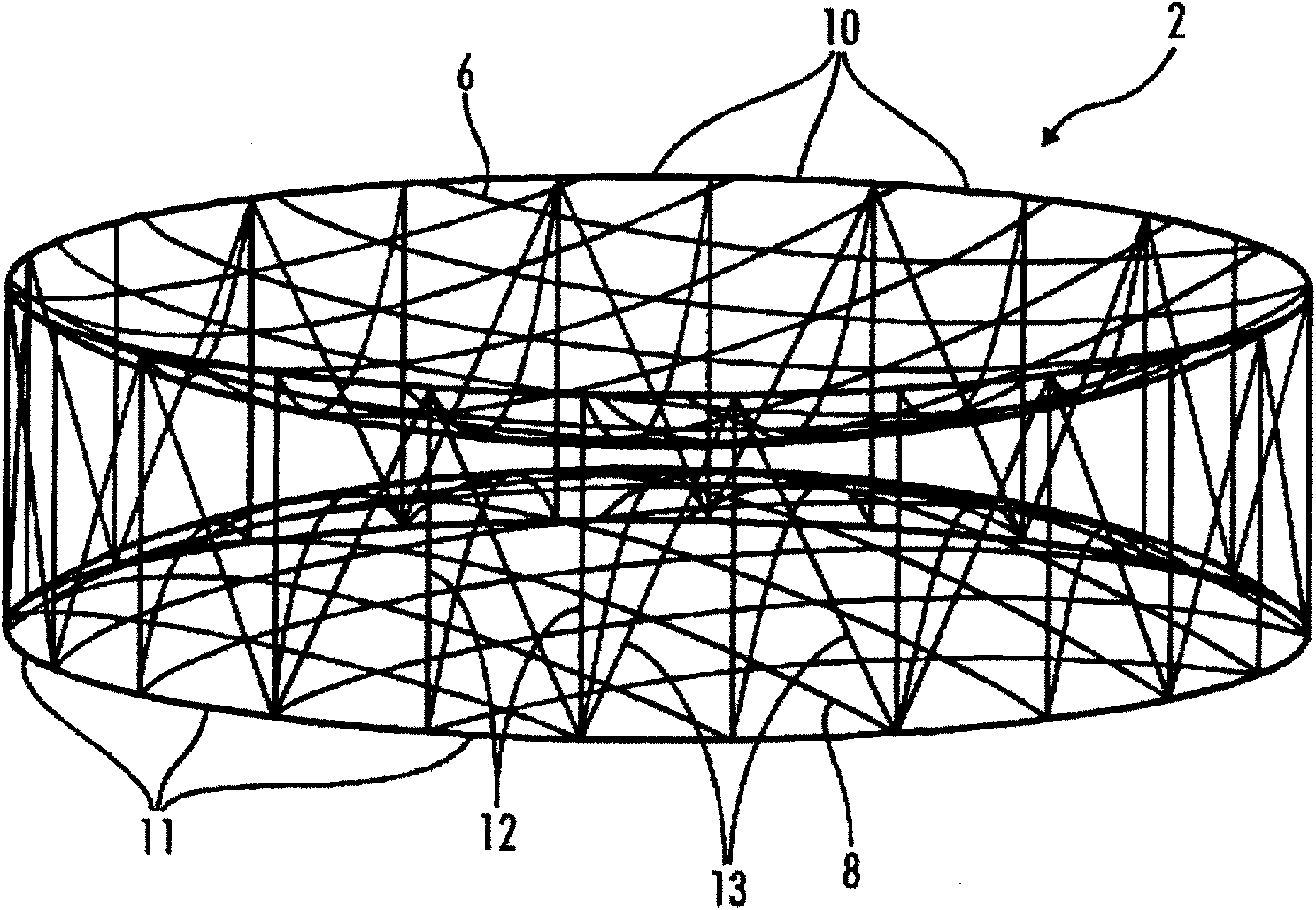
[0040] refer to figure 2 with image 3 , the rectangular truss reflective curved surface unfolding device of the present invention includes: ring connecting joints 1 and folding rings 2, both of which are plural, and the specific number is determined according to the diameter of the unfolded curved surface. in:
[0041] The structure of ring connection joint 1 is as follows Figure 10 (a) and Figure 10 As shown in (b), it is composed of a pair of bevel gear structures 101, 102 and a pair of splints 103, 104. Angles of 160-180 degrees are set at the splints, so that the ring structure can rotate around a fixed axis in the process of being folded up to unfolded. The size of the angle is related to the number of ring rods, which is determined according to the formula: θ=180*(1-2 / n), where n is the number of ring rods, and n≥4. A torsion spring 106 is installed on the gear shaft 105 of the bevel gear structure, and a positioning guide groove 107 is provided on the platform ...
Embodiment 2
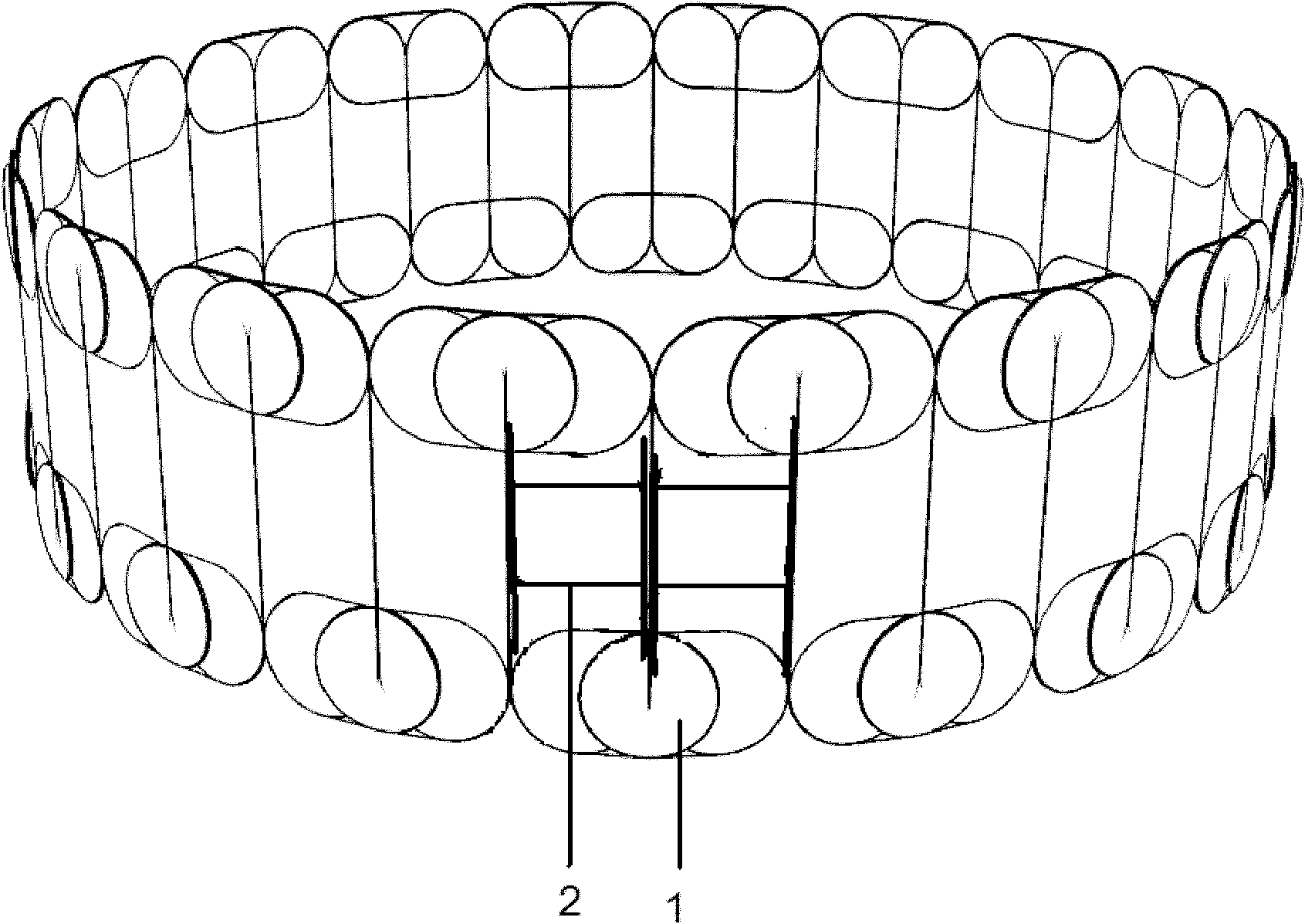
[0044] refer to figure 2 with Figure 4 , the rectangular truss-type refracting curved surface unfolding device of the present invention includes: a ring connecting joint 1 and a folding ring 2, both of which are plural, and the specific number is determined according to the diameter of the unfolded curved surface. in:
[0045] The structure of ring connection joint 1 is as follows Figure 10 (a) and Figure 10 As shown in (b), it is composed of a pair of bevel gear structures 101, 102 and a pair of splints 103, 104. Angles of 160-180 degrees are set at the splints, so that the ring structure can rotate around a fixed axis in the process of being folded up to unfolded. The size of the angle is related to the number of ring rods, which is determined according to the formula: θ=180*(1-2 / n), where n is the number of ring rods, and n≥4. A torsion spring 106 is installed on the gear shaft 105 of the bevel gear structure, and a positioning guide groove 107 is provided on the p...
Embodiment 3
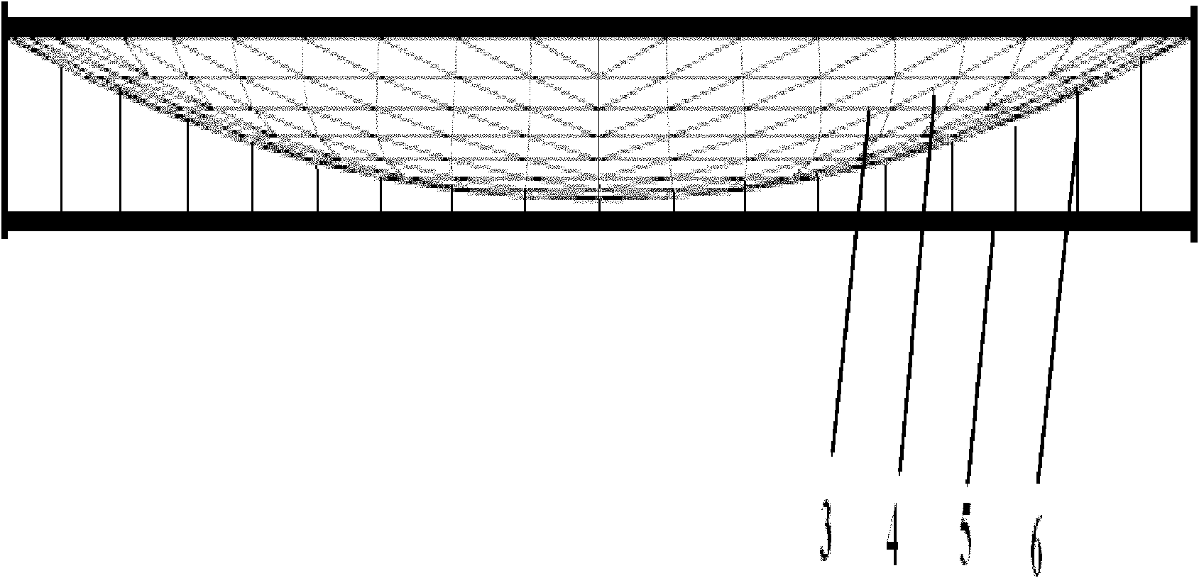
[0048] refer to Figure 5 with Image 6 , the equilateral triangular truss reflective curved surface unfolding device of the present invention includes: ring connecting joint 1 and folding ring 2, both of which are plural, and the specific number is determined according to the diameter of the unfolded curved surface. in:
[0049] The structure of ring connection joint 1 is as follows Figure 10 (a) and Figure 10 As shown in (b), it is composed of a pair of bevel gear structures 101, 102 and a pair of splints 103, 104. Angles of 160-180 degrees are set at the splints, so that the ring structure can rotate around a fixed axis in the process of being folded up to unfolded. The size of the angle is related to the number of ring rods, which is determined according to the formula: θ=180*(1-2 / n), where n is the number of ring rods, and n≥4. A torsion spring 106 is installed on the gear shaft 105 of the bevel gear structure, and a positioning guide groove 107 is provided on the ...
PUM
| Property | Measurement | Unit |
|---|---|---|
| Areal density | aaaaa | aaaaa |
| Areal density | aaaaa | aaaaa |
Abstract
Description
Claims
Application Information