

System and method for testing radio frequency (RF) of long term evolution (LTE) base station
A technology of radio frequency test system and base station, which is applied in the field of radio frequency test system of LTE base station, can solve the problems such as the inability to meet the test requirements of LTE system, and achieve the effects of shortening test time, saving test cost, and saving manpower and material resources
- Summary
- Abstract
- Description
- Claims
- Application Information
AI Technical Summary
Problems solved by technology
Method used
Image

Examples
Embodiment 1
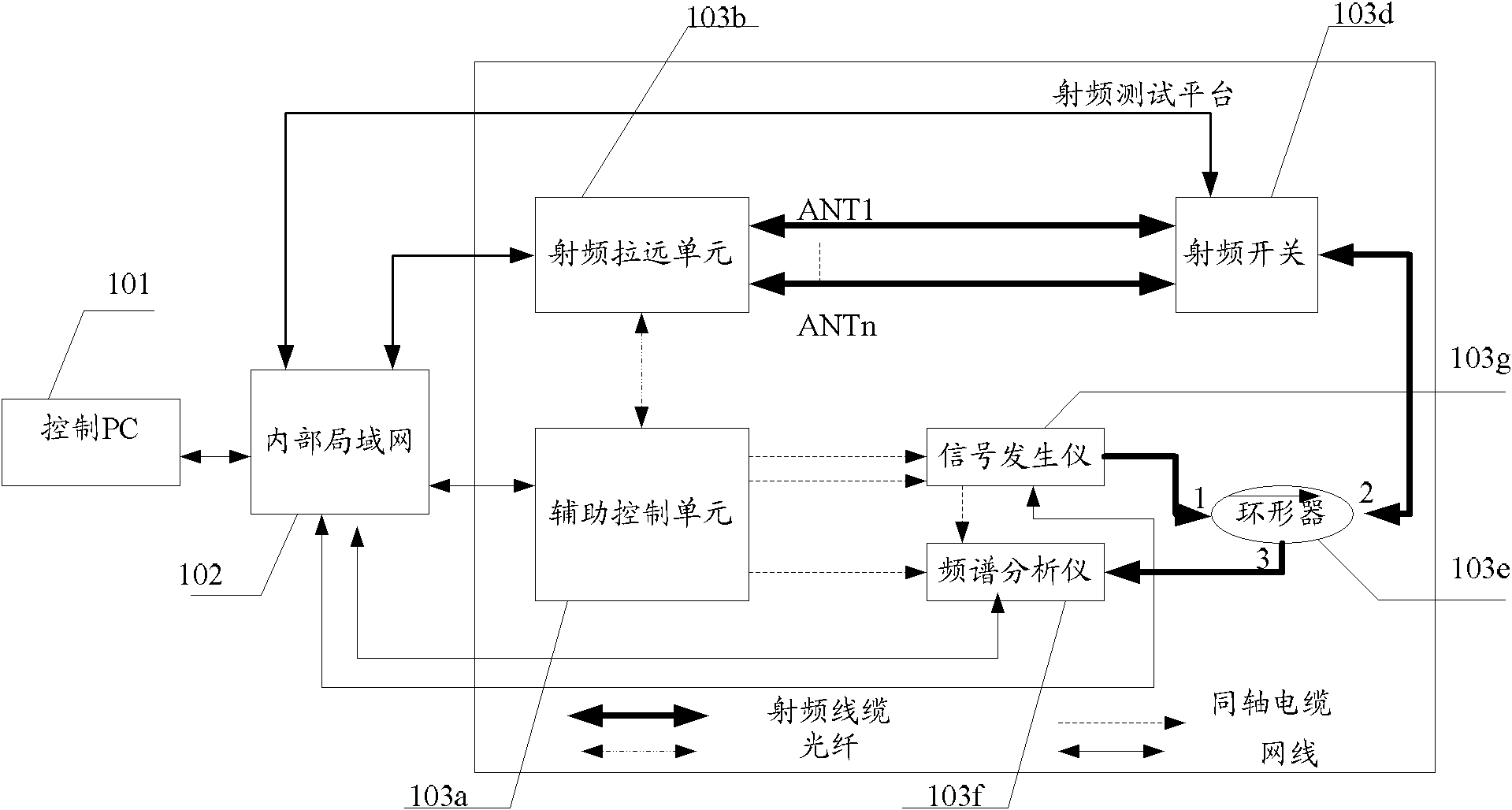
[0025] see figure 1 , which is a schematic structural diagram of an embodiment of a radio frequency testing system for an LTE base station in the present application. Such as figure 1 As shown, the system includes: control PC101, internal LAN 102, auxiliary control unit 103a, remote radio unit RRU103b, radio frequency switch 103d, circulator 103e, spectrum analyzer 103f and signal generator 103g, wherein,
[0026] The control PC 101 is used to issue control commands to the spectrum analyzer 103f, the signal generator 103g, the radio frequency switch 103d, the RRU 103b and the auxiliary control unit 103a through the internal local area network 102;
[0027] Wherein, the internal LAN 102 is composed of multiple Ethernet switches. Signal generator 103f, spectrum analyzer 103g, control PC 101, radio frequency switch 103d, auxiliary control unit 103a and RRU 103b are connected to the internal LAN 102 through network cables, so that the control PC 101 sends control commands throug...
Embodiment 2
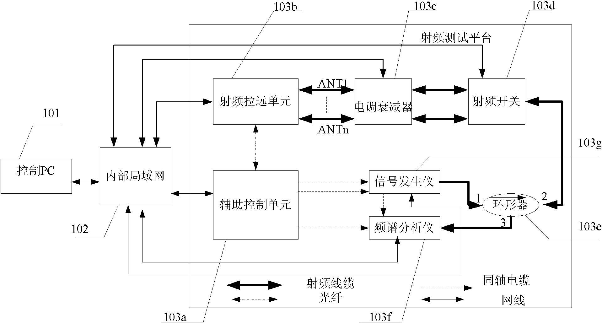
[0053] Usually, the power of the baseband signal output from the remote radio unit RRU is too large, which may burn out the spectrum analyzer. Similarly, the power of the radio frequency signal on the radio frequency antenna port selected by the radio frequency switch may also be very large. Therefore, the embodiment of the present application also provides a radio frequency test system of an LTE base station. The difference between the present embodiment and the first embodiment is that an electronically adjustable attenuator is added between the remote radio unit RRU and the radio frequency switch. see image 3 , which is a schematic structural diagram of another embodiment of a radio frequency test system for an LTE base station in the present application. The system includes: a control PC 101, an internal LAN 102, an auxiliary control unit 103a, a radio remote unit RRU103b, an electric control attenuator 103c, RF switch 103d, circulator 103e, spectrum analyzer 103f and si...
Embodiment 3
[0066] The embodiment of the present application also provides a radio frequency testing system of an LTE base station. The difference between this embodiment and the second embodiment is that a channel simulator is added between the remote radio unit RRU and the electronically adjustable attenuator. see Figure 4, which is a structural schematic diagram of another embodiment of a radio frequency test system for an LTE base station in the present application. The system includes: a control PC 101, an internal local area network 102, an auxiliary control unit 103a, a radio remote unit RRU103b, a channel simulator 103h, and an electrical Attenuator 103c, RF switch 103d, circulator 103e, spectrum analyzer 103f and signal generator 103g. This implementation introduces a channel simulator 103h for simulating various wireless channel propagation environment models and testing radio frequency performance indicators under the control of the control PC 101 . Since the control PC 101,...
PUM
 Abstract
Description
Claims
Application Information