Eureka AIR delivers breakthrough ideas for toughest innovation challenges, trusted by R&D personnel around the world.

LED fluorescent lamp

A technology of LED fluorescent lamps and LED light sources, applied in lampshades, light sources, electric light sources, etc., can solve the problems of poor heat dissipation, high local temperature, hot hands, etc., to achieve good heat dissipation, enhance stability, and reduce temperature.

Inactive Publication Date: 2011-04-13
MASS TECH (HK) LTD
View PDF4 Cites 6 Cited by
  • Summary
  • Abstract
  • Description
  • Claims
  • Application Information

AI Technical Summary

Problems solved by technology

Although the LED array structure can meet the lighting requirements, it also produces problems such as heat concentration, excessive local temperature, and affecting the stability of the circuit control system.
Since there is no special heat conduction and heat dissipation device, the heat generated by multiple LED light sources cannot be effectively dissipated, so that the temperature of the shell of the lamp will be relatively high, and there will be a danger of scalding when people touch it; moreover, the temperature High also makes the lamp more susceptible to damage
[0004] At present, many technical solutions have been proposed to solve the heat dissipation problem of LED lamps, but some of these technical solutions have poor heat dissipation effects, and some have good heat dissipation effects, but the cost is too high and the structure is complicated.
For example, China's invention patent application number 200910011246.8, the patent application titled "Loop-type heat pipe radiator heat dissipation LED lighting lamp", discloses a LED lighting lamp that uses a loop-type heat pipe radiator to dissipate heat. The principle of small thermal resistance and high thermal conductivity of the radiator solves the problem of LED heat dissipation, but this heat dissipation method is costly and complex in structure

Method used


Image

  • LED fluorescent lamp
  • LED fluorescent lamp
  • LED fluorescent lamp

Examples


Embodiment Construction

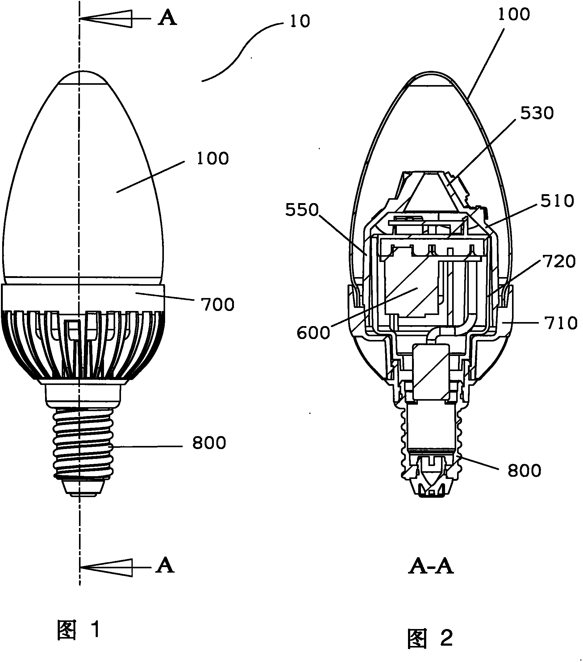
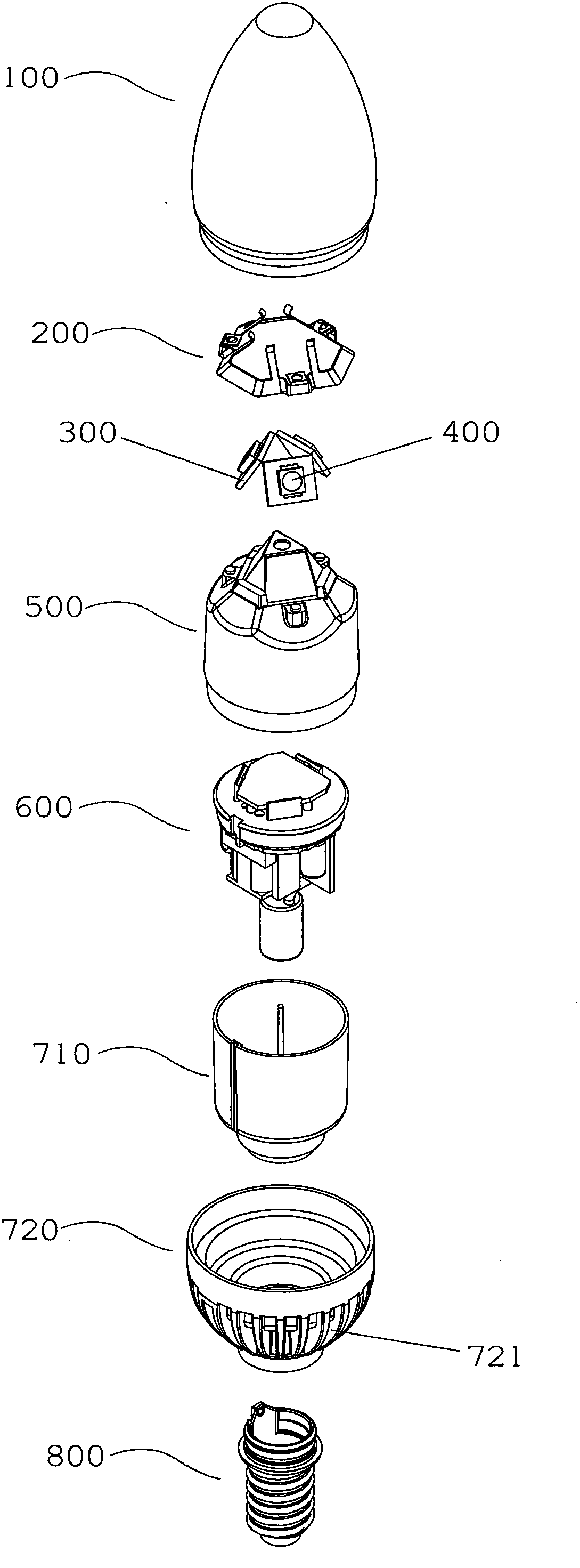
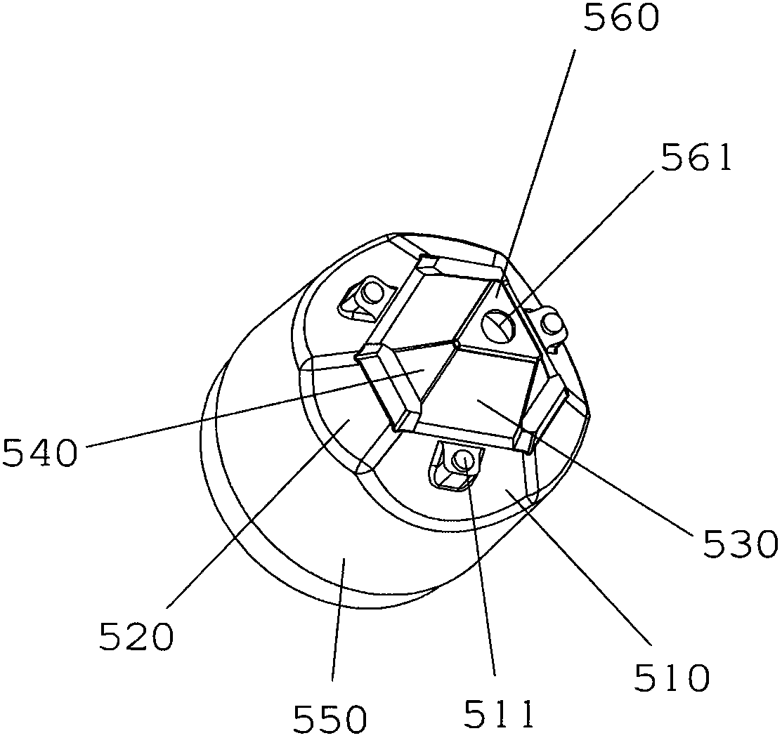
[0031] refer to Figure 1 to Figure 3 , the figure shows an LED fluorescent lamp 10 as a preferred embodiment of the present invention, the fluorescent lamp 10 includes a glass bulb 100, three LED light sources 400, three light source panels 300, a heat conducting device 500, a control circuit 600, and a rear cover 700 And the lamp head 800.

[0032] The glass bubble 100 can be a transparent glass bubble, or a glass bubble sprayed with silica gel, a twisted glass bubble, a frosted glass bubble, etc. can be selected as required. The lamp holder 800 can be designed as lamp holders of various sizes as required, such as E11, E12, E14, E17, E26, E27 and so on. The control circuit 600 is not the main point of the present invention, and will not be described in detail here.

[0033] The LED light source can consist of one or more LEDs. In this embodiment, each of the three LED light sources 400 is composed of three chip LEDs, which are respectively fixed on three light source pane...


PUM


Abstract

The invention provides a LED fluorescent lamp, comprising a lamp head, a glass bulb and a control circuit, at least two LED light sources, at least two light source panels for fixing the LED light sources, a heat conduction device and a rear cover. The heat conduction device comprises at least two heat conduction base plates capable of inclining towards its vertical center line direction and at least two light source panels are respectively permanently connected with at least two heat conduction base plates in the heat conduction way and the bottom of the heat conduction base plate extends downwards to form a housing cavity. The rear cover comprises a shell and a hollow column for housing the control circuit and the shell is in closed joint with the heat conduction device by an annular interface, thus the heat conduction device is scarfed with the rear cover in the heat conduction way and a plurality of heat radiation slices are arranged on the outer side surface of the rear cover. The light source panel, the heat conduction device, the shell of the rear cover and the heat radiation slices form a good heat conduction and heat radiation path. The LED fluorescent lamp has good heat conduction and heat radiation and effectively solves the over-heat problem of the LED light source.

Description

technical field [0001] The invention relates to the field of lighting fixtures. More specifically, the present invention relates to an LED fluorescent lamp used as a lighting fixture, the LED fluorescent lamp has high luminous efficiency and good heat dissipation. Background of the invention [0002] As a solid light source with great development potential, LED has attracted more and more attention due to its advantages of long life, firm structure, low power consumption and flexible shape and size since its birth in the 1960s, and has gradually replaced Traditional high-voltage halogen lamps are used in various lighting fields. However, the LED lamp itself generates a relatively large amount of heat when it is working, resulting in a large light attenuation and shortening the service life of the LED lamp, thus limiting the application range of the LED lamp in the lighting field to a certain extent. [0003] Because the brightness and power of a single LED light source are...

Claims


Application Information

Patent Timeline
Patent Type & Authority Applications(China)
IPC IPC(8): F21S8/00F21V17/00F21V19/00F21V23/00F21V29/00F21Y101/02
CPCF21V29/2225F21V3/049F21V23/02F21Y2101/02Y02B20/386F21K9/00F21V29/004F21K9/135F21Y2111/007F21V3/0418F21K9/232F21V3/061F21V29/77F21V29/83F21Y2107/40F21Y2115/10
Inventor 胡安华
Owner MASS TECH (HK) LTD
Why Eureka
Eureka Blog
Learn More