Flue gas-based combined desulfuration and denitration method and special device for method

A technology for desulfurization and denitrification and flue gas, which is applied in the direction of separation methods, chemical instruments and methods, and separation of dispersed particles. It can solve the problems of difficult control of flue gas flow, non-uniform distribution, and low denitrification efficiency, so as to improve desulfurization and denitrification efficiency. , easy processing, and the effect of improving denitrification efficiency

Active Publication Date: 2011-04-20
CCTEG CHINA COAL RES INST
View PDF4 Cites 30 Cited by
  • Summary
  • Abstract
  • Description
  • Claims
  • Application Information

AI Technical Summary

Problems solved by technology

The disadvantage of this invention is that the flue gas flow in a reactor is not easy to control, and part of the flue gas after desulfurization is easy to stick to the reactor wall and directly enter the chimney from the denitrification outlet. This part of the flue gas is not mixed with NH 3 Mix evenly, resulting in low denitrification efficiency; spray NH 3 The mouth is divided into upper and lower two, under the action of smoke exhaust, NH 3 It cannot be evenly distributed in the upper denitrification activated coke bed, resulting in low NO removal rate in flue gas

Method used


Image

  • Flue gas-based combined desulfuration and denitration method and special device for method
  • Flue gas-based combined desulfuration and denitration method and special device for method
  • Flue gas-based combined desulfuration and denitration method and special device for method

Examples


Embodiment 1

[0035] Example 1, flue gas combined desulfurization and denitrification device

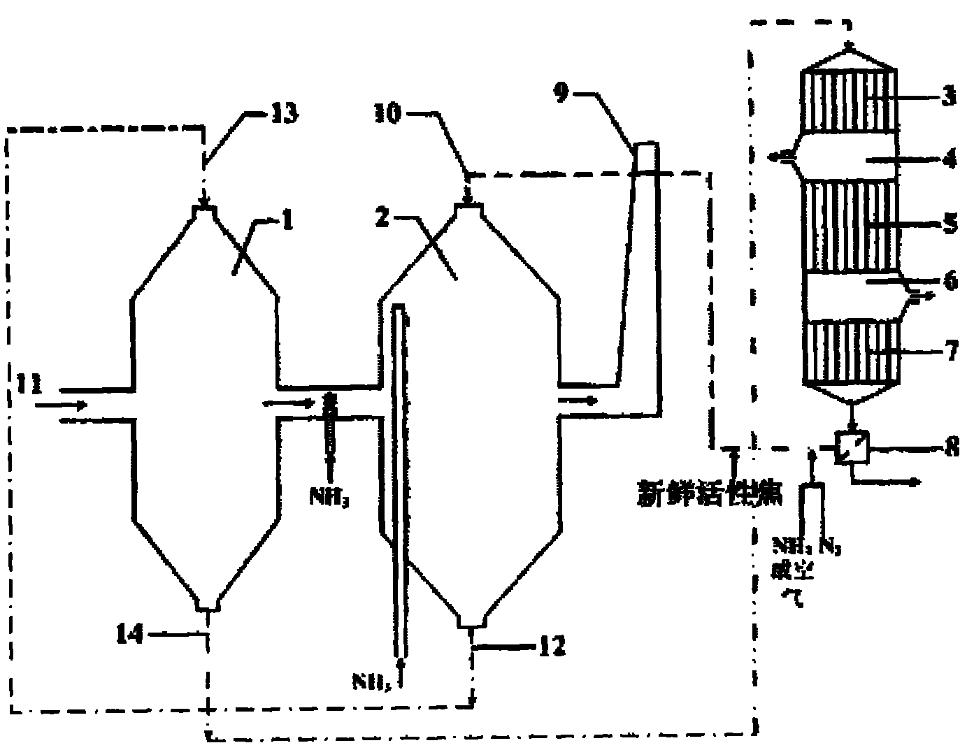
[0036] The schematic diagram of the device is shown in figure 1 As shown, each mark in the figure is as follows: 1 desulfurization reactor, 2 denitrification reactor, 3 NO desorption zone, 4 NO enrichment zone, 5 SO 2 Desorption zone, 6 SO 2 Enrichment zone, 7 active coke cooling zone, 8 screening device, 9 flue gas outlet, 10 active coke denitrification reactor inlet, 11 flue gas inlet, 12 active coke denitrification reactor outlet, 13 active coke desulfurization reactor inlet, 14 Active coke desulfurization reactor outlet.

[0037] The combined flue gas desulfurization and denitration device of the present invention comprises a desulfurization reactor 1 and a denitration reactor 2, the desulfurization reactor 1 and the denitration reactor 2 are connected in series, and the volume of the denitration reactor 2 is 1.5 times the volume of the desulfurization reactor 1; Reactor 1 is located on the...

Embodiment 2

[0039] Example 2, flue gas combined desulfurization and denitrification device

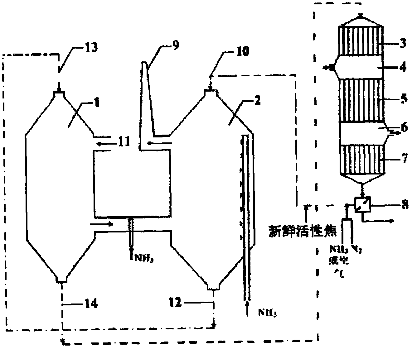
[0040] The schematic diagram of the device is shown in figure 2 As shown, each mark in the figure is as follows: 1 desulfurization reactor, 2 denitrification reactor, 3 NO desorption zone, 4 NO enrichment zone, 5 SO 2 Desorption zone, 6 SO 2 Enrichment zone, 7 active coke cooling zone, 8 screening device, 9 flue gas outlet, 10 active coke denitrification reactor inlet, 11 flue gas inlet, 12 active coke denitrification reactor outlet, 13 active coke desulfurization reactor inlet, 14 Active coke desulfurization reactor outlet.

[0041] The flue gas combined desulfurization and denitration device of the present invention comprises a desulfurization reactor 1 and a denitration reactor 2, the desulfurization reactor 1 and the denitration reactor 2 are connected in series, and the volume of the denitration reactor 2 is 1.2 times the volume of the desulfurization reactor 1; Reactor 1 is located on th...

Embodiment 3

[0043] Embodiment 3, use the flue gas combined desulfurization and denitrification device of embodiment 1 to carry out desulfurization and denitrification

[0044] Add 500t of initial activated coke from the inlet 10 of the denitrification reactor to the denitrification reactor 2 in the combined flue gas desulfurization and denitrification device of Example 1. The active coke moves from top to bottom in the denitration reactor 2 by gravity and The NH spray installed in the adsorption denitrification reactor 2 3 NH emitted from the device 3 , remove NO and SO from flue gas 2 Then come out from the outlet 12 of the active coke denitrification reactor and enter the desulfurization reactor 1 through the inlet 13 of the active coke desulfurization reactor. The active coke moves from top to bottom in the desulfurization reactor 1 by gravity, absorbing NO and SO 2 ; Then come out from the outlet 14 of the active coke desulfurization reactor and enter the regeneration reactor throu...


PUM


Abstract

The invention discloses a flue gas-based desulduratoin and denitration method and a special device for the flue gas-based desulduratoin and denitration method. The special device comprises a denitration reactor body and a desulphurization reactor body, wherein the side wall of the desulphurization reactor body is provided with a flue inlet; the desulphurization reactor body and the denitration reactor body are communicated in parallel; the volume of the denitration reactor body is 1-2 times that of the desulphurization reactor body; the communicating position of the desulphurization reactor body and the denitration reactor body is provided with a device for spraying NH3; the top of the denitration reactor body is provided with a denitration reactor inlet for active coke; the bottom of thedenitration reactor is provided with a denitration reactor outlet for the active coke; the top of the desulphurization reactor is provided with a desulphurization reactor inlet for the active coke; the bottom of the desulphurization reactor is provided with a desulphurization reactor outlet for the active coke; and the denitration reactor outlet for the active coke is communicated with a desulphurization reactor inlet for the active coke through a pipeline, and the desulphurization reactor outlet for the active coke is communicated with a regeneration reactor. The invention also provides a method for flue gas desulfurization and denitration by using the device.

Description

technical field [0001] The invention relates to a flue gas purification method and a device thereof, in particular to a flue gas combined desulfurization and denitrification method and a special device thereof. Background technique [0002] SO in coal flue gas 2 and NO x The environmental pollution caused by acid rain and photochemical smog has become a serious problem affecting the living environment of human beings. With the improvement of environmental protection requirements in recent years, while controlling SO 2 and NO x Emissions requirements are more pressing. Compared with the single application of traditional desulfurization and denitrification technologies, combined desulfurization and denitrification technologies have advantages in terms of economy and resource utilization efficiency. Coal-burning pollution in my country is becoming more and more serious. It is imperative to vigorously develop low-cost and high-efficiency coal-burning pollution prevention and ...

Claims


Application Information

Patent Timeline
Patent Type & Authority Applications(China)
IPC IPC(8): B01D53/75B01D53/56B01D53/50
Inventor 孙仲超熊银伍梁大明傅翔李雪飞董卫国李兰廷李艳芳吴涛张科达
Owner CCTEG CHINA COAL RES INST
Why Eureka
Try Eureka