

Mechanical coolant pump
A coolant pump, mechanical technology, used in engine cooling, coolant flow control, mechanical equipment, etc., can solve problems such as pivot seals stuck, achieve low sliding friction, and improve energy efficiency.
- Summary
- Abstract
- Description
- Claims
- Application Information
AI Technical Summary
Problems solved by technology
Method used
Image

Examples
Embodiment Construction
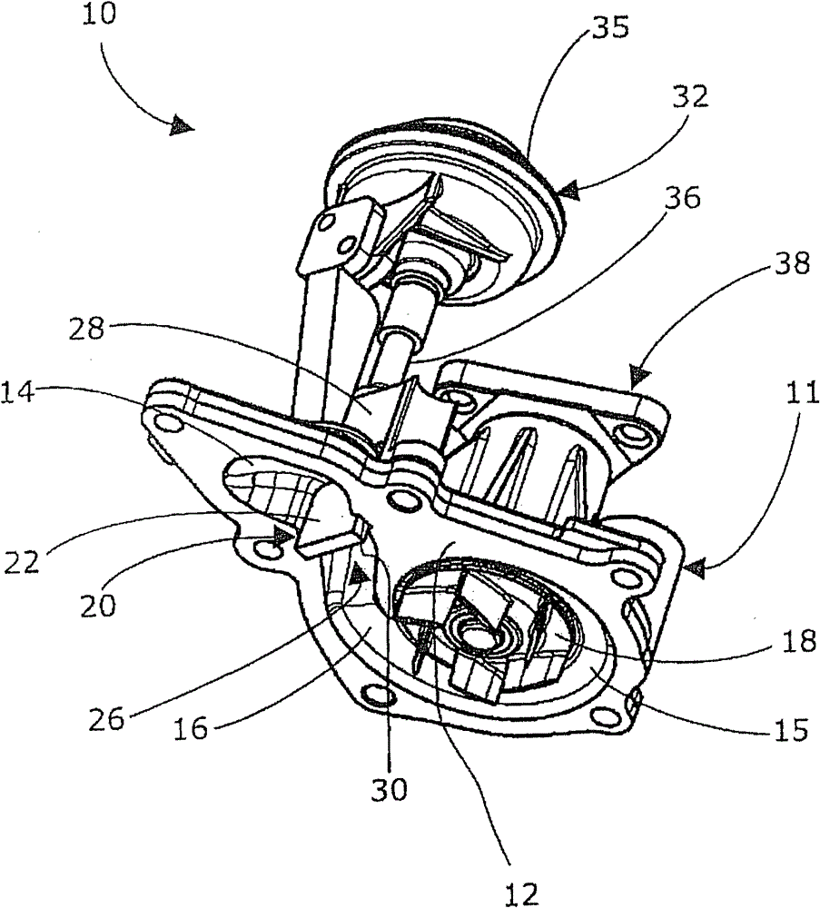
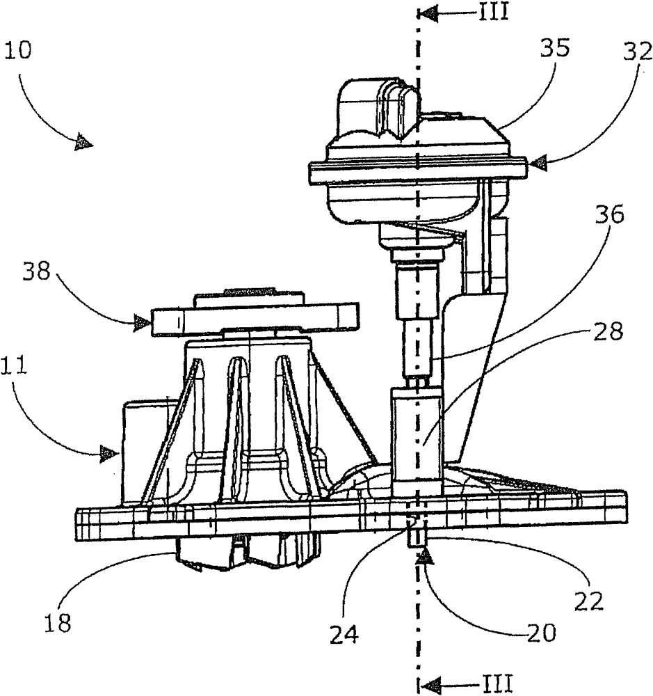
[0022] exist figure 1 In , a mechanical coolant pump 10 for an internal combustion engine is shown. The mechanical coolant pump 10 comprises a main pump body 11 whereby the main pump body is mounted directly to the engine block via a flange 12 or may have a cover plate (not shown).
[0023] The main pump body 11 houses a rotatable impeller 18 which sucks in coolant axially and pumps the coolant radially outward into a volute 15 . The impeller 18 is driven by the combustion engine using a drive belt (not shown) which drives a drive wheel 38 of the mechanical coolant pump 10 . The coolant flows from the volute 15 into the outlet channel 16 due to centrifugal force and passes through the outlet valve 20 to the outlet opening 14 . An outlet valve 20 is located at the end of the outlet channel 16 .
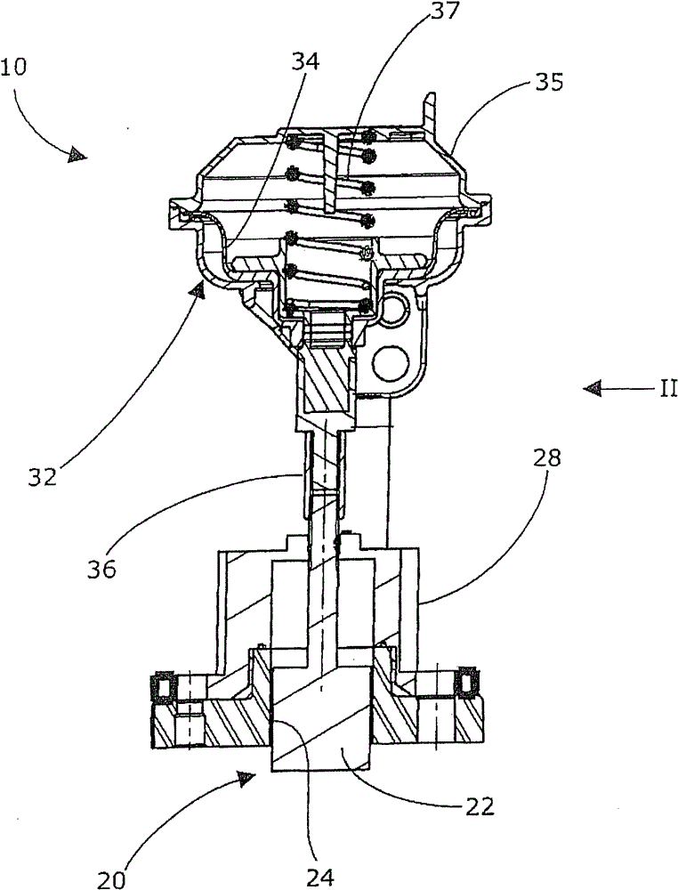
[0024] The outlet valve 20 includes a movable flat valve plate 22 which is movable within the cross-section of the outlet channel 16 through a passing slit 24 through an outlet chan...
PUM
 Abstract
Description
Claims
Application Information