Infrared thermal imager testing system

A technology of infrared thermal imager and test system, which is applied in the direction of instruments, measuring devices, scientific instruments, etc., can solve the problems of reduced reliability, poor temperature uniformity, large error value, etc., to improve stability and reliability, improve Accuracy, the effect of improving flexibility

Inactive Publication Date: 2011-04-20
YANTAI RAYTRON TECH
View PDF3 Cites 22 Cited by
  • Summary
  • Abstract
  • Description
  • Claims
  • Application Information

AI Technical Summary

Problems solved by technology

[0003] 1. Under high and low temperature / variable temperature conditions, the environment has a greater impact on the test system, and the entire test system will undergo thermal changes, so the test system itself is an uncertain system
Various mechanical components, optical devices, blackbody systems, etc. related to the performance test system will change with the change of ambient temperature, which will lead to poor temperature uniformity, increased difficulty in temperature measurement and control, mechanical deformation, fog and other defects
In short, there are too many uncertain factors in this test system, which will reduce the accuracy and reliability of the performance measurement of the whole machine, and even the test results cannot explain the performance of the thermal imager at all.
[0004] 2. Because the test system in the prior art is greatly affected by high and low temperature, and the system stability is poor, this makes the test system in the prior art unable to be used for testing optical performance indicators that require high system stability, such as high and low temperature Stability of the lower optical axis
[0005] 3. The measurement function of the test system in the prior art is single, and can only complete the measurement of subjective MRTD. However, it is found through experiments that there are also errors in the results of MRTD measurement, and the error value is large, which is not comparable with the results of room temperature measurement. Therefore, the measurement results Lost the purpose
[0007] 5. Since the entire test system is in high and low temperature, humid heat environment for a long time, the service life of the test system is shortened

Method used


Image

  • Infrared thermal imager testing system
  • Infrared thermal imager testing system
  • Infrared thermal imager testing system

Examples


Embodiment Construction

[0048] The principles and features of the present invention are described below in conjunction with the accompanying drawings, and the examples given are only used to explain the present invention, and are not intended to limit the scope of the present invention.

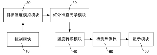
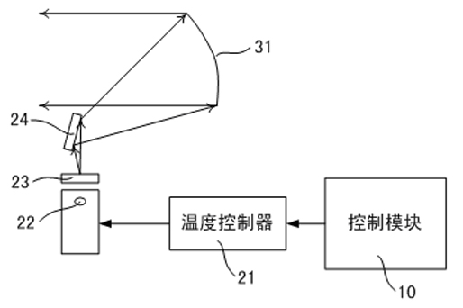
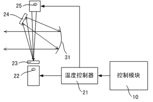
[0049] like figure 1As shown, the infrared thermal imager testing system includes a control module 10 , a target temperature simulation module 20 , an infrared collimation optical module 30 , a temperature conversion module 40 , and a display module 50 . The control module 10 is connected to the target temperature simulation module 20 to control the target temperature simulation module 20 to output a simulated radiation temperature signal; the control module 10 is also connected to the temperature conversion module 40 to control the temperature conversion module 40 to select a test environment. Wherein, the infrared collimation optical module 30 receives the radiation temperature signal, converts the radiation tempe...


PUM


Abstract

The invention discloses an infrared thermal imager testing system, which comprises a control module, a target temperature simulation module, an infrared collimating optical device, a temperature conversion module and a display module, wherein the control module is connected with the target temperature simulation module and the temperature conversion module respectively, and controls the output of simulated radiation temperature signals and the selection of testing environments; the infrared collimating optical module converts the radiation temperature signals into parallel light radiation temperature signals and outputs the parallel light radiation temperature signals to the temperature conversion module; the temperature conversion module is used for creating a room-temperature testing environment and a high/low-temperature testing environment, and projecting the received parallel light radiation temperature signals onto a to-be-tested thermal imager positioned in the room-temperature testing environment or the high/low-temperature testing environment; and the display module displays an infrared thermograph transmitted by the to-be-tested thermal imager. Therefore, the performance of the thermal imager is tested in the room-temperature environment and the high/low-temperature environment in the same testing system. Simultaneously, the temperature simulation accuracy is improved, and the stability, reliability and flexibility of the testing system are also improved.

Description

technical field [0001] The invention relates to the field of infrared testing, in particular to an infrared thermal imager testing system. Background technique [0002] The traditional thermal imager performance test system under high and low temperature / variable temperature conditions is to place the thermal imager and the performance test system in a high and low temperature box. That is, the characteristic of the existing technology is that the entire system (including the temperature difference source, target, target disk and its rotating mechanism, collimator, loading platform, optical bench and other mechanical devices, etc.) is placed in a high and low temperature box, This will have the following disadvantages: [0003] 1. Under high and low temperature / variable temperature conditions, the environment has a greater impact on the test system, and the entire test system will undergo thermal changes, so the test system itself is an uncertain system. Various mechanica...

Claims


Application Information

Patent Timeline
Patent Type & Authority Applications(China)
IPC IPC(8): G01J5/00
Inventor 李欣范芸赵秀娟胡佳伟马彦静徐莹
Owner YANTAI RAYTRON TECH
Why Eureka
Try Eureka