Supercharge Your Innovation With Domain-Expert AI Agents!

Inductive energy-acquiring device on high-voltage cable

A technology for inductive energy extraction and high-voltage cables, applied in circuit devices, electrical components, electromagnetic wave systems, etc., can solve problems such as hidden safety hazards, large differences in outer diameter, and large quality, and achieve the effect of improving energy and good energy extraction effect.

Active Publication Date: 2012-10-10
PNC PROCESS SYSTEMS CO LTD +1
View PDF2 Cites 0 Cited by
  • Summary
  • Abstract
  • Description
  • Claims
  • Application Information

AI Technical Summary

Problems solved by technology

[0011] However, after research, it has been found that using the above methods of the prior art to obtain the same electric energy from the high-voltage overhead lines and high-voltage power cables with the same load respectively requires the use of induction coil cores with the same cross-sectional area, but the outer diameter of the overhead lines and power cables The size of the induction coil core applied to the power cable is much larger than that of the overhead line, and the mass is too large to be installed on the cable; and the above method cannot achieve an open circuit voltage of less than 50V, which has potential safety hazards
It can be seen that the power-taking device applied to high-voltage overhead lines is not suitable for power cables

Method used


Image

  • Inductive energy-acquiring device on high-voltage cable
  • Inductive energy-acquiring device on high-voltage cable
  • Inductive energy-acquiring device on high-voltage cable

Examples


Embodiment 1

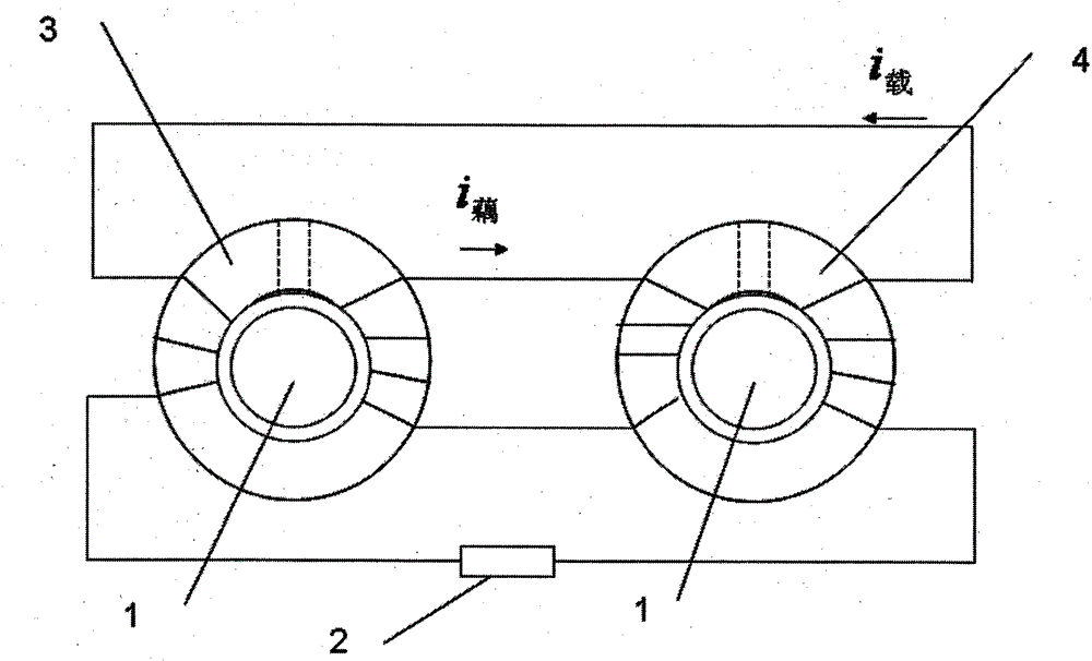
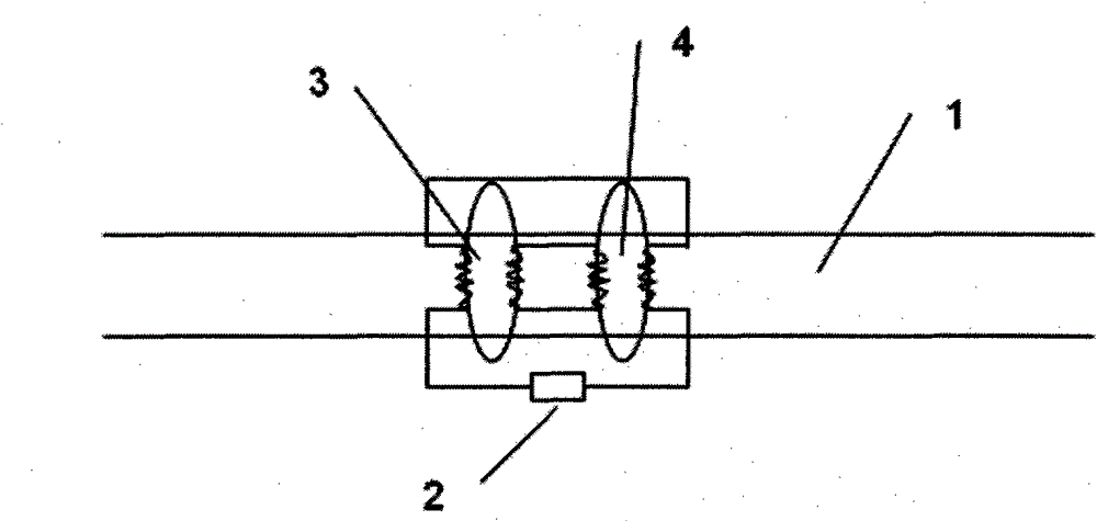
[0041] see first figure 1 and figure 2 , figure 1It is a structural schematic diagram of Embodiment 1 of an induction energy harvesting device on a high-voltage cable of the present invention, figure 2 It is a schematic diagram of coil connection in Embodiment 1 of an induction energy harvesting device on a high-voltage cable of the present invention. It can be seen from the figure that in this embodiment, the induction energy harvesting device on the high-voltage cable mainly includes a magnetic ring set on the high-voltage cable 1 structurally. The magnetic ring set includes two magnetic rings, each of which is provided with an air gap, one of the magnetic rings in the magnetic ring set is the main magnetic ring 4 , and the other is the secondary magnetic ring 3 . The purpose of leaving an air gap on the magnetic ring is to prevent magnetic saturation from affecting the energy harvesting effect. Here the main magnetic ring and the auxiliary magnetic ring are made of th...

Embodiment 2

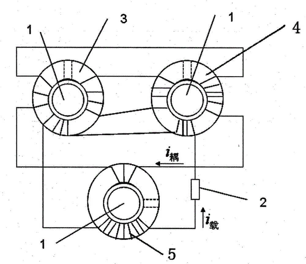
[0051] please look again image 3 and Figure 4 , image 3 It is a structural schematic diagram of Embodiment 2 of an induction energy harvesting device on a high-voltage cable of the present invention, Figure 4 It is a schematic diagram of coil connection in Embodiment 2 of an induction energy harvesting device on a high-voltage cable of the present invention. It can be seen from the figure that in this embodiment, one more magnetic ring is added on the basis of the two magnetic rings in Embodiment 1. The most important thing is to use the feedback coupling structure again, so that the output energy of energy harvesting can be further increased efficiently. Its specific structure is: under the premise of the structure of the energy-taking device in Embodiment 1, when making further improvements, it is still on the original high-voltage cable 1, and the original external load position is replaced with a magnetic cable of the same specification Ring, this magnetic ring is t...

Embodiment 3

[0055] please look again Figure 5 , Figure 5 It is a structural schematic diagram of Embodiment 3 of an induction energy harvesting device on a high-voltage cable of the present invention. It can be seen from the figure that in this embodiment, one more magnetic ring is added on the basis of the three magnetic rings in Embodiment 2. The most important thing is to use the feedback coupling structure again, so that the output energy of energy harvesting can be further increased efficiently.

[0056] Its specific structure is: under the premise of the structure of the energy-taking device in Embodiment 2, when making further improvements, it is still on the original high-voltage cable 1, and the original external load is replaced with a magnetic cable of the same specification. ring, this magnetic ring is a new main magnetic ring 6, and the original main magnetic ring 5 becomes a secondary magnetic ring, the new main magnetic ring 6 is provided with an output coil and a coupli...


PUM


Abstract

The invention relates to an inductive energy-acquiring device on a high-voltage cable. The inductive energy-acquiring device comprises magnetic loop triads sheathed on the high-voltage cable, wherein the magnetic loop set comprises two magnet rings, each magnet ring is provided with an air gap, one magnetic loop of the magnet ring set is a main magnet ring while the other one is a secondary magnet ring, the main magnetic loop is provided with an output winding and a coupling coil, the secondary magnetic loop is provided with a feedback coil and a coupling coil, the output winding on the main magnetic loop is connected with the feedback coil on the secondary magnetic loop as well as an external load, so as to form an output loop, and the coupling coil on the main magnetic loop is connectedwith the coupling coil on the secondary magnetic loop, so as to form a coupling loop. The inductive energy-acquiring device provided by the invention can utilize current rate of change of the output loop to improve energy while the open-circuit voltage of the inductive electricity-getting device is in a safe range, so that the area of an iron core is smaller and the energy-acquiring effect is obvious.

Description

technical field [0001] The invention relates to induction power collection, in particular to a 24-hour all-weather energy device on a high-voltage cable. Background technique [0002] The high-voltage power cable is the main hub for the transmission and distribution of electric energy in the underground power grid. It is generally laid underground in the form of direct burial, pipe arrangement, and cable tunnel. Therefore, it is necessary to install a large number of secondary low-voltage equipment on the power cable and its surrounding environment. Such as monitoring equipment and control equipment to ensure the normal and safe operation of power cables. Because the transmission distance of the power cable is long, the laying method is special, and the laying environment is harsh, it is a big problem to supply power to its secondary low-voltage equipment. [0003] At present, the widely used power supply methods include: battery power supply, mains power supply, line curre...

Claims


Application Information

Patent Timeline
Patent Type & Authority Patents(China)
IPC IPC(8): H02J17/00H02J50/10
Inventor 汤大伟陆文娟赵浩
Owner PNC PROCESS SYSTEMS CO LTD
Features
  • R&D
  • Intellectual Property
  • Life Sciences
  • Materials
  • Tech Scout
  • Unparalleled Data Quality
  • Higher Quality Content
  • 60% Fewer Hallucinations
Learn More