
Forward and reverse passive inter-modulation (PIM) testing device and method for isolator

A passive intermodulation and testing device technology, applied in transmission monitoring, electrical components, transmission systems, etc., can solve the problem of affecting the accuracy of passive intermodulation testing of high-end isolators, increasing the burden of power amplifiers and power supplies, and inconvenient production workshop batches Testing and other issues to achieve the effect of improving operability and testing efficiency, improving transmission efficiency and performance, and facilitating mass production testing

Inactive Publication Date: 2011-04-20
镇江市澳华测控技术有限公司
View PDF2 Cites 26 Cited by
  • Summary
  • Abstract
  • Description
  • Claims
  • Application Information

AI Technical Summary

Problems solved by technology

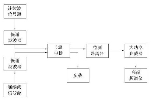
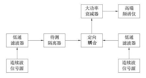
[0003] The purpose of the present invention is to provide a forward and reverse passive intermodulation test device and method for an isolator, which solves the problem in the prior art that different test platforms need to be built for the forward and reverse passive intermodulation test, which is not convenient for batch testing in the production workshop. Problems, large residual intermodulation in the system, which affects the accuracy of passive intermodulation testing for high-end isolators, the problem of increasing the burden on the power amplifier and power supply when using a 3dB bridge combination, the test must use a high-performance spectrum analyzer and Questions that require mathematical operations to obtain test results

Method used


Image

  • Forward and reverse passive inter-modulation (PIM) testing device and method for isolator
  • Forward and reverse passive inter-modulation (PIM) testing device and method for isolator
  • Forward and reverse passive inter-modulation (PIM) testing device and method for isolator

Examples


Embodiment Construction

[0018] The present invention will be further described below in conjunction with the accompanying drawings and specific embodiments.

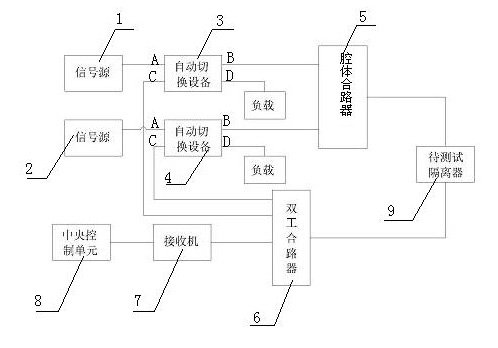
[0019] Such as image 3 As shown, the isolator forward and reverse passive intermodulation test device of the present invention includes a first continuous wave signal source 1, a second continuous wave signal source 2, a first automatic switching device 3, a second automatic switching device 4, a cavity Body combiner 5, duplex combiner 6, receiver 7, central control unit 8, the first continuous wave signal source 1 is connected to the A end of the first automatic switching device 3, the second continuous wave signal source 2 It is connected with the A terminal of the second automatic switching device 4, the B terminal of the first automatic switching device 3 and the B terminal of the second automatic switching device 4 are connected with the cavity combiner 5, and the C terminal of the first automatic switching device 3 , the C end of the se...


PUM


Abstract

The invention discloses a forward and reverse passive inter-modulation (PIM) testing device and method for an isolator. The testing device comprises a first continuous wave signal source, a second continuous wave signal source, first automatic switching equipment, second automatic switching equipment, a cavity combiner, a duplex combiner, a receiver and a central control unit. The testing method comprises the following steps: setting the testing mode to be forward or reverse testing; setting carrier frequency and carrier power required in a test; testing the forward or reverse PIM level of the isolator; and calculating the difference value between a PIM level value and a carrier power value, wherein, the difference value is the relative inter-modulation level. In the invention, different test platforms are not required in the case of the forward and reverse PIM testing, thus improving the maneuverability and the testing efficiency, lowering the residual inter-modulation of a system, improving the testing accuracy, eliminating power consumption of a 3dB electrical bridge, and enhancing the transmission efficiency and performance of a radio frequency signal; and a central processingunit is adopted instead of a frequency spectrograph, so the testing result can be directly obtained.

Description

technical field [0001] The invention relates to a passive intermodulation test device and method, in particular to a forward and reverse passive intermodulation test device and method for an isolator, and belongs to the technical field of communication equipment. Background technique [0002] When two signal frequencies or multiple signal frequencies pass through the same passive RF transmission system (connectors, filters, transmission lines, antennas, isolators, waveguides, etc.) A nonlinear component is generated between them, which is the passive intermodulation product. The power level of passive intermodulation is generally low and decreases rapidly as the order increases. With the rapid development of mobile communication, people have higher and higher requirements on the coverage of mobile communication service signals. Therefore, there are relatively high requirements on the performance indicators of mobile communication equipment, especially the passive intermodu...

Claims


Application Information

Patent Timeline
IPC IPC(8): H04B17/00H04B17/14
Inventor 陶长英邹小芳
Owner 镇江市澳华测控技术有限公司
Learn More