Protective element and method for manufacturing the same

A technology for protecting components and manufacturing methods, which is applied in the manufacturing of fuses, electrical components, emergency protection devices, etc., can solve problems such as deteriorating the responsiveness of current cut-off actions, and achieve the effect of good responsiveness

Active Publication Date: 2011-04-20
DEXERIALS CORP
View PDF10 Cites 19 Cited by
  • Summary
  • Abstract
  • Description
  • Claims
  • Application Information

AI Technical Summary

Problems solved by technology

[0012] In addition, there is a problem that the temperature of the liquidus point or the solidus

Method used


Image

  • Protective element and method for manufacturing the same
  • Protective element and method for manufacturing the same
  • Protective element and method for manufacturing the same

Examples


Embodiment

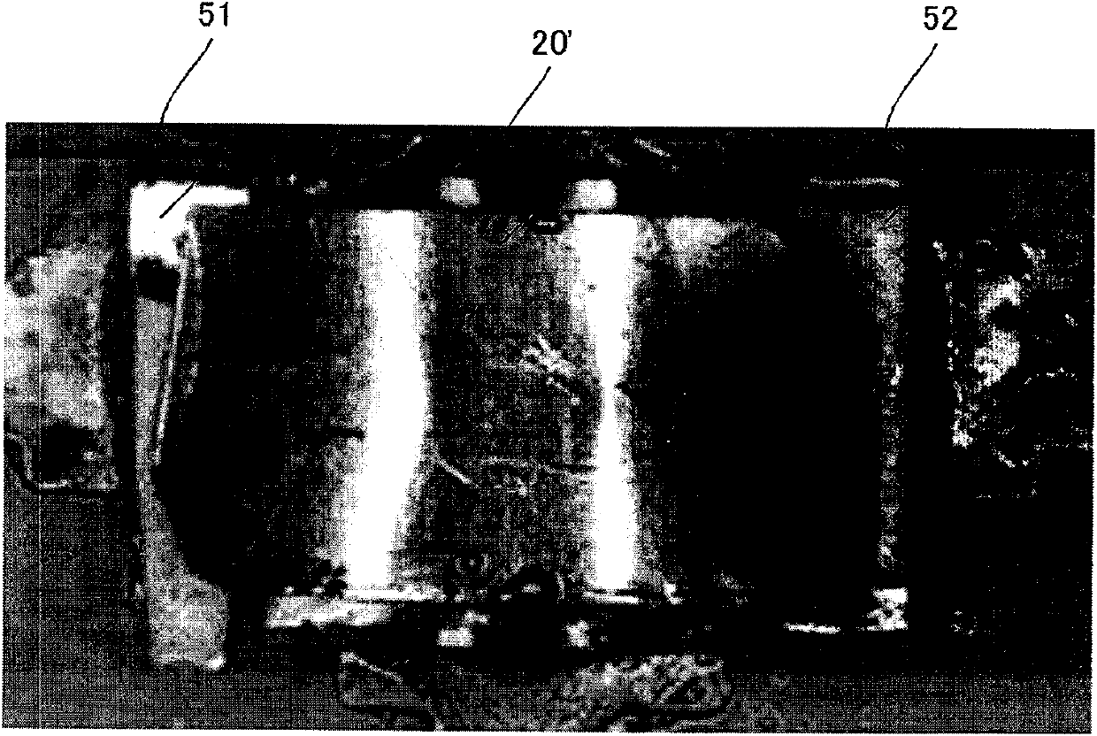
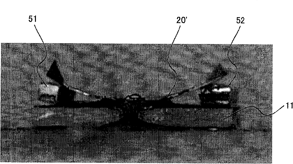
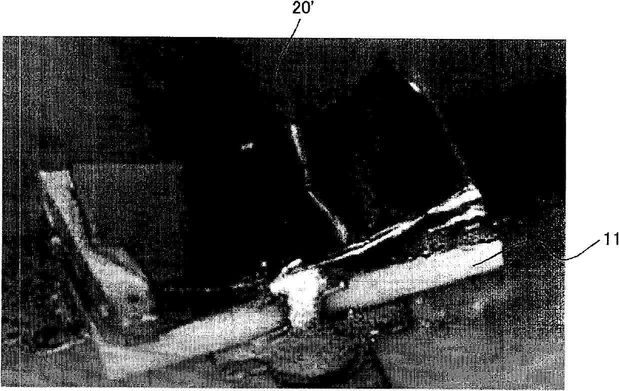
[0107] The inventors of the present invention actually produced a protection element, and conducted a current conduction test to evaluate both the current interruption operation of heating of the heating resistor and generation of overcurrent. made with Figure 10 The composition shown shall prevail for the protection element. Specifically, if Figure 11 to Figure 13 As shown, as the reference distance member 40, two wedge members 51, 52 corresponding to the above wedge members 41, 42 are prepared, these wedge members 51, 52 are inserted under the elastic member 20', and the elastic member 20' The central portion is bent into a substantially U-shape and is in an elastic state. In addition, the elastic member 20' is formed of a flat material made of super phosphor copper C5191-H, with a thickness of 0.05 mm, a width of about 2.5 mm, and a length of about 5 mm.

[0108] First, such a protective element is actually heated using a predetermined heating operation test device to ...


PUM


Abstract

Provided is a protective element which can be applied to reflow mounting and can ensure good responsiveness to current interruption operation even if the liquid phase point or the solid phase point of solder used is higher than a mounting temperature. A protective element wherein a resilient member (20) is bonded through solder (21) to a second conductor (15) and conduction electrode terminals (16, 17) formed on a predetermined substrate (11) in order to divide a conduction passage into a plurality of current interruption parts. The solder (21) has a liquid phase point higher than the mounting temperature when the protective element is mounted on a protection object apparatus. The resilient member (20) is soldered to the second conductor (15) and the conduction electrode terminals (16, 17) while holding stress of such a degree as the resilient member is separated from at least one of the second conductor (15) and the conduction electrode terminals (16, 17) by being deformed even under such a state where the solder (21) does not melt completely.

Description

technical field [0001] The present invention relates to a protection element for cutting off current when a machine to be protected is abnormal, and a manufacturing method thereof. Background technique [0002] The protective element used to prevent overcurrent when the equipment to be protected is abnormal is known as a chip-shaped protective element in which a low-melting-point metal body (fuse unit) is provided on a substrate. Such a protection element melts the fuse unit by passing an overcurrent to the fuse unit when an abnormality occurs. Therefore, in the protective element, the melted fuse unit is used on the electrode due to its good wettability to the surface of the electrode on which the fuse unit is mounted. As a result, in the protection element, the fuse unit melts open, thereby cutting off the current. [0003] In addition, the protective element used not only for overcurrent but also for overvoltage protection is a chip-shaped protective element in which a ...

Claims


Application Information

Patent Timeline
IPC IPC(8): H01H37/76H01H69/02H01H85/06
CPCH01H2085/466H01H85/36H01H83/10H01H2085/0414H01H85/46H01H2037/762H01H83/20
Inventor 米田吉弘
Owner DEXERIALS CORP
Why Eureka
Try Eureka