Vortex prevention device for relieving fluid vortex

A fluid vortex and anti-vortex technology, applied in the field of vortex, can solve problems such as difficult to eliminate

Inactive Publication Date: 2011-04-27
NORTHEASTERN UNIV
View PDF0 Cites 5 Cited by
  • Summary
  • Abstract
  • Description
  • Claims
  • Application Information

AI Technical Summary

Problems solved by technology

[0004] It can be seen from production practice that the vortex of m

Method used


Image

  • Vortex prevention device for relieving fluid vortex
  • Vortex prevention device for relieving fluid vortex
  • Vortex prevention device for relieving fluid vortex

Examples


Embodiment Construction

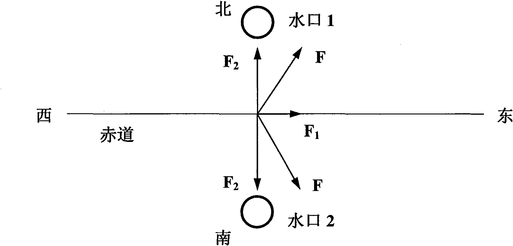
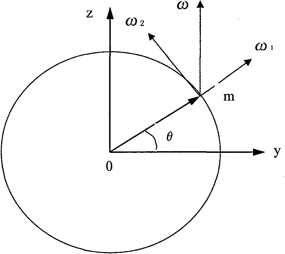
[0024] Due to the centrifugal force generated by the rotation of the earth, the magnitude and direction of the force are different according to the different geographical locations in the northern and southern hemispheres. The strength and direction of the vortex produced by the fluid are also different. The vortex in the southern hemisphere is clockwise, and the vortex in the northern hemisphere is counterclockwise. The present invention has different placement schemes according to the different directions of the vortex.

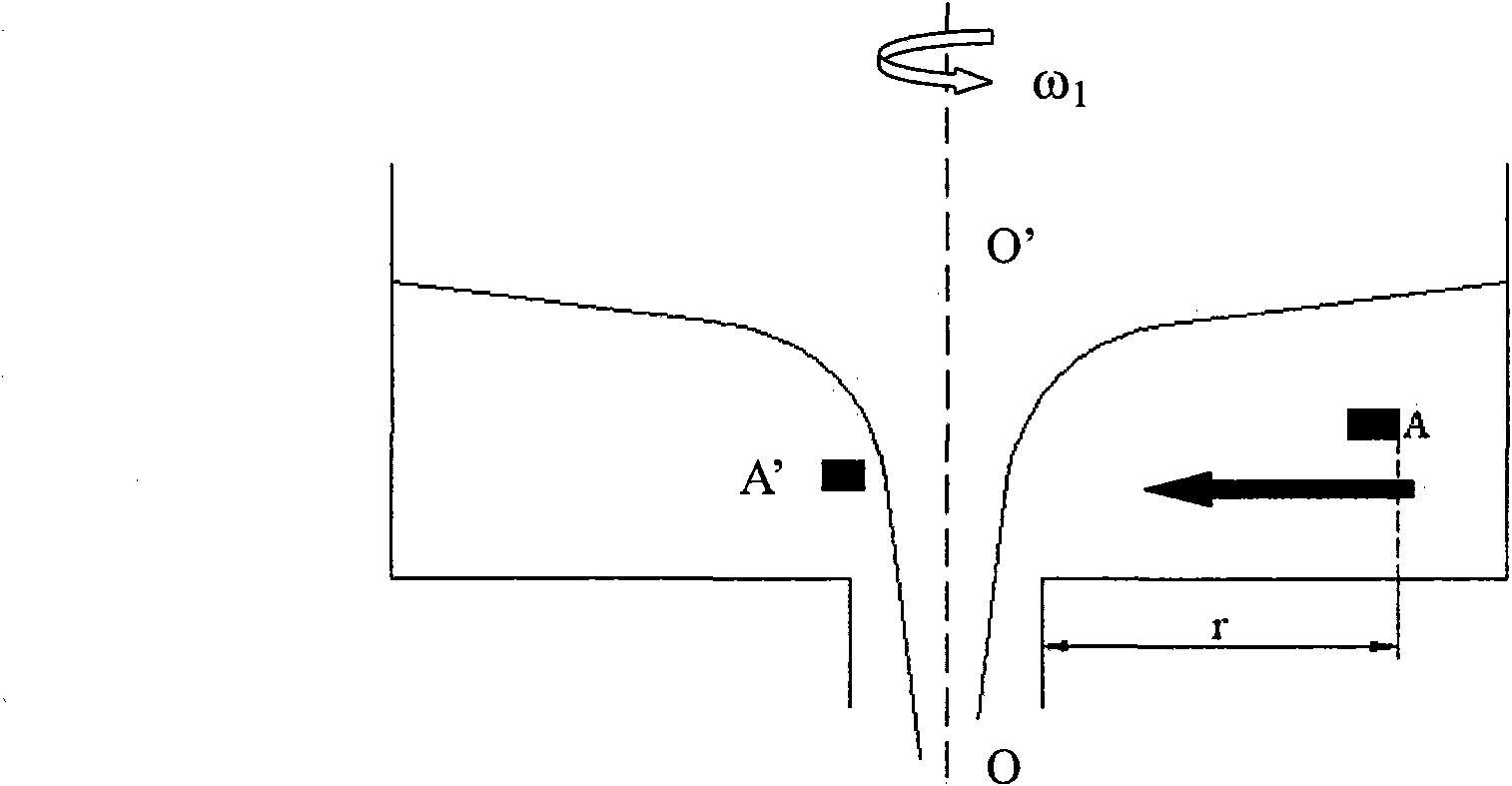
[0025] based on the following Figure 4 A, B, C and Figure 5 A, B, and C specifically illustrate the implementation of the anti-rotation device.

[0026] Figure 4 A is the anti-swirl device for reducing fluid vortex when it is located in the northern hemisphere. Its structure is: 3 refractory bricks made of anti-erosion refractory materials are built around the nozzle as shown in the figure. Refractory bricks 1, 2 and 3 have the same cross section, wh...


PUM


Abstract

The invention relates to a vortex prevention device for relieving a fluid vortex, and provides a device which can prevent fluid from producing vortex and the vortex from being expanded, which can be applied to various fields and applied to a position close to a ladle or tundish casting nozzle in the metallurgical industry. The device is characterized in that: one or more table bodies which are made of a corrosion-resistant refractory material are placed close to the ladle or tundish casting nozzle; and the section of each table body can have a rectangular shape or other polygonal shapes. The theoretical basis of the device is that: due to geocentric deflecting force produced by earth rotation and gravitational attraction, a funnel-shaped vortex is formed close to the nozzle at the final stage of casting of molten steel. Different placement schemes are available for different geographic positions. The scheme is that: a flow field which is completely reverse to that produced by the vortex is forcibly arranged at the bottom of a container, so the formation of the vortex is suppressed. Through water model experiments, obvious effect is achieved, and particularly the run-through height is halved. The device substantially suppresses the expansion of the vortex, so the purity of the molten steel and the metal yield can be simultaneously improved. The device provides powerful guarantee for subsequent tundish metallurgy and continuous casting production.

Description

technical field [0001] The invention relates to a vortex generated during fluid flow, in particular to a vortex preventing device during the transfer of molten steel from one container to another in the metallurgical industry, such as a ladle or tundish casting process. Background technique [0002] As we all know, with the progress of society and the development of science and technology, the requirements for steel quality are getting higher and higher. This makes the production of high-quality steel mainly focus on reducing the content of impurity elements and controlling inclusions in steel. Therefore, every link of the whole process must strictly control the quality of molten steel. In the modern steelmaking process, the vortex slag produced when the molten steel is transferred from one container to another has been a problem that cannot be completely solved for a long time. Its existence makes it difficult to remove the inclusions in the steel, reduces the content of b...

Claims


Application Information

Patent Timeline
IPC IPC(8): B22D41/50
Inventor 于景坤蔺瑞颜正国毛飞雄
Owner NORTHEASTERN UNIV
Why Eureka
Try Eureka