Metal plate polishing device
A technology of metal plates and vertical plates, applied in the direction of grinding drive devices, metal processing equipment, grinding machines, etc., can solve the problems of difficult cleaning of worktables and plate surfaces, increase the labor intensity of operators, and affect the stability of test data, etc., to achieve Superior uniformity and quality stability, lower grinding costs, simple structure
- Summary
- Abstract
- Description
- Claims
- Application Information
AI Technical Summary
Problems solved by technology
Method used
Image
Examples
Embodiment 1
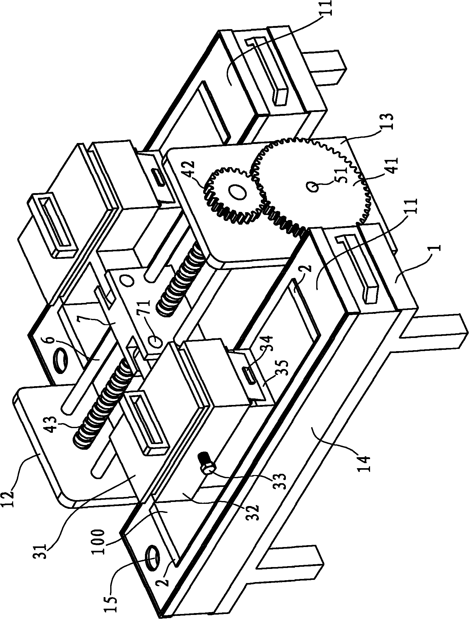
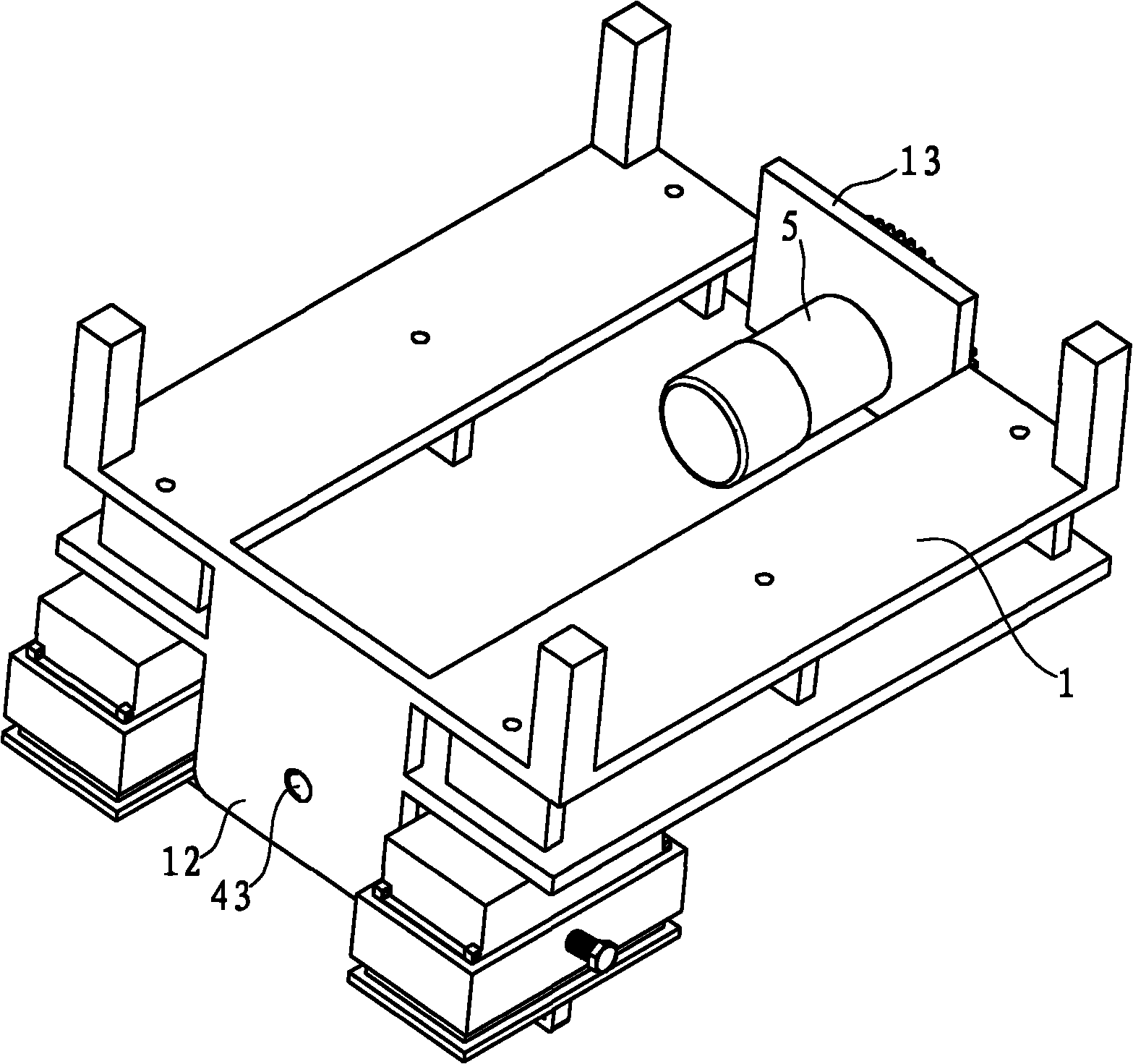
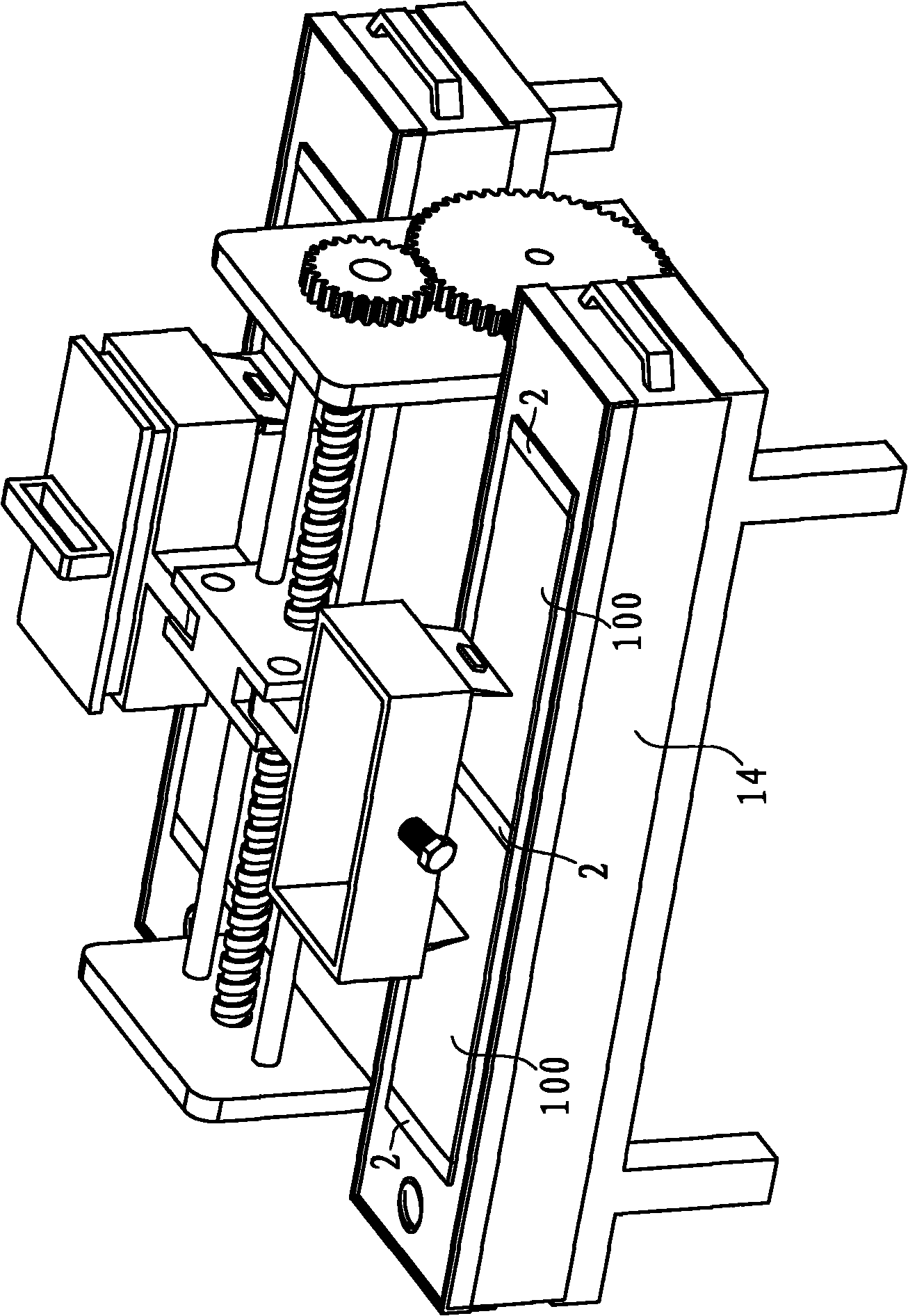
[0038] Example 1, such as figure 1 , figure 2 , image 3 and Figure 4 As shown, the metal plate grinding device in the present embodiment includes a base frame 1, a motor 5, a load-bearing mechanism 3 and a transmission mechanism, and the upper end surface of the base frame 1 has two grinding tables 11 for grinding of the respective load-bearing mechanisms 3, and are arranged at intervals There are vertical boards 12 and vertical boards 13. The base frame 1 is located at the bottom of the grinding table 11 and is provided with a water collection tank 14. The grinding table 11 is provided with a water guide hole 15 that can introduce water on the grinding table 11 into the water collection tank 14. When the water is full , can be pulled out from the base frame 1 and disposed of. The motor 5 can rotate forward and backward, and the load-bearing mechanism 3 can move back and forth and is arranged on the polishing table 11. The transmission mechanism has a power input end con...
Embodiment 2
[0046] Example 2, such as Figure 7 As shown, the grinding table 11 in this embodiment is provided with an insertion hole, the stop block 2 is inserted in the insertion hole and the bottom of the grinding table 11 is exposed, and the base frame 1 is located below the grinding table 11 and is provided with a mounting plate 15. The mounting plate 15 is provided with a threaded hole, and an adjusting bolt 21 whose top is against the bottom of the blocking block 2 is arranged in the threaded hole from bottom to top. In this way, after the blocking block 2 wears out, it can be supplemented by lifting the adjusting bolt 21 upwards. The present embodiment is not provided with a water collection tank, other structures can refer to embodiment 1.
PUM
 Abstract
Description
Claims
Application Information
 - R&D
- Intellectual Property
- Life Sciences
- Materials
- Tech Scout
- Unparalleled Data Quality
- Higher Quality Content
- 60% Fewer Hallucinations
Browse by: Latest US Patents, China's latest patents, Technical Efficacy Thesaurus, Application Domain, Technology Topic, Popular Technical Reports.
© 2025 PatSnap. All rights reserved.Legal|Privacy policy|Modern Slavery Act Transparency Statement|Sitemap|About US| Contact US: help@patsnap.com


