Low-friction conveying channel and forming method thereof

A conveying channel and low-friction technology, applied in the field of conveying channel and its forming, can solve the problems of high relative molecular weight, difficult forming process, small flow rate, etc., achieve safety inspection, convenient maintenance and replacement, avoid R&D investment, and reduce cross-section Effect

Active Publication Date: 2012-08-22
BEIJING UNIV OF CHEM TECH
View PDF6 Cites 0 Cited by
  • Summary
  • Abstract
  • Description
  • Claims
  • Application Information

AI Technical Summary

Problems solved by technology

Due to its extremely high relative molecular weight, high melt viscosity, low flow rate, and very difficult molding processing, the current molding methods of this material are mainly compression molding and plunger extrusion molding. The existing processing technology and equipment are still It cannot meet the processing and manufacturing of large-scale and complex parts. At present, these two materials are limited to the extrusion molding of small plates, sheets or rods.

Method used


Image

  • Low-friction conveying channel and forming method thereof
  • Low-friction conveying channel and forming method thereof
  • Low-friction conveying channel and forming method thereof

Examples


Embodiment 1

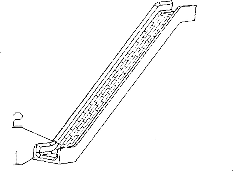
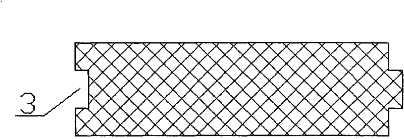
[0021] A low-friction conveying channel of the present invention is composed of two parts, a support base plate 1 and a face profile 2, such as figure 1 As shown; according to different materials and transportation requirements, the support base plate 1 can be made into different cross-sectional shapes. For example, when transporting liquids such as oil and mud, a closed channel should be used, and the support base plate 1 should be made into a circular pipe with a cross section; coal transport For large particles such as food, ore, a semi-closed channel should be used, and the supporting base 1 is made into a U-shaped structural channel; in order to improve the strength and rigidity of the supporting base 1, the supporting base 1 is generally made of metal materials, which can be It is formed by rolling or welding, or connected by screws or rivets; the support base plate 1 forms the support frame of the conveying channel along the conveying path, and the support base plate 1 i...

Embodiment 2

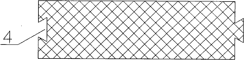
[0031] see Figure 4 , the structure, working principle and effect of this embodiment and embodiment 1 are basically the same. The difference is that the channel section adopts a closed section. The section shape of the face profile is fan-shaped, and the surface in contact with the material is arc-shaped. When the face profiles are spliced, the side is coated with adhesive, which is beneficial to form a closed structure after splicing, so as to transport liquids and other occasions that require a closed structure. This structure is not suitable for conveying fluid with high pressure, because the sealing is not easy to guarantee.

[0032] The low-friction conveying channel of the present invention can not only be used for conveying materials in various industries, but also can be used for slideways in playgrounds, kindergartens and the like.

[0033] The forming method of a low-friction conveying channel of the present invention is as follows: firstly, the supporting base pl...


PUM


Abstract

The invention discloses a low-friction conveying channel and a forming method thereof. The conveying channel consists of a support bottom plate and face sections, wherein the support bottom plate is provided with a support frame of the conveying channel along a conveying path; the face sections are positioned on the support bottom plate and are long strip sections with the same section shape and size; concave-convex grooves, which are rectangular grooves, dovetail grooves, semi-dovetail grooves, T-shaped grooves or sawtooth grooves, are formed on the side faces of the face sections; the internal surface of the conveying channel is formed by splicing the face sections; and the face sections are made of materials with low surface friction coefficient, such as ultrahigh molecular weight polyethylene and polytetrafluoroethylene. The problem that a large conveying channel is difficult to process is solved; due to a double-layer structure, an outer layer still can be normally operated when an inner layer is severely damaged, and great accidents are avoided; and the low-friction conveying channel is conveniently subjected to regular safety inspection and maintenance and replacement, and the reliability and safety of the conveying channel are greatly increased.

Description

technical field [0001] The invention relates to a conveying channel and a forming method thereof for transporting materials in various industries, in particular to a conveying channel and a forming method thereof for wear-resistant and low-friction applications. Background technique [0002] Conveying channels are often used for long-distance transportation of materials, and are often found in ports, docks, mines, coal mines, grain depots and other occasions. The conveying channel can transport pulverized coal, slag, mud, oil, grain, etc. over a long distance. Usually, this conveying channel is made of steel. The steel plate is processed by hot rolling and cold rolling to make conveying channels with different cross-sectional shapes, and then corresponding post-processing processes are carried out according to different usage occasions. Like transporting oil and mud, closed channels are often used, and semi-closed channels are often used to transport large particles such as...

Claims


Application Information

Patent Timeline
Patent Type & Authority Patents(China)
IPC IPC(8): B65G11/16B65G11/02F17D1/08
Inventor 杨卫民边智谢鹏程丁玉梅
Owner BEIJING UNIV OF CHEM TECH
Why Eureka
Try Eureka