Integrated composite spinning device of ring spinning frame

A spinning frame and ring spinning technology, applied in the field of pneumatic gathering devices, can solve problems such as grid ring deviation, yarn hairiness fluctuation, detachment, etc., to ensure consistency and accuracy, reduce strength fluctuations, and install accurately Effect

Active Publication Date: 2011-04-27
常州市同和纺织机械制造有限公司
View PDF9 Cites 13 Cited by
  • Summary
  • Abstract
  • Description
  • Claims
  • Application Information

AI Technical Summary

Problems solved by technology

However, due to the fact that the installation groove of the accumulating roller is not fully enclosed in the circumferential direction, the accuracy of the accumulating roller after installation cannot be easily maintained with the negative pressure accumulating tube, so the consistency of the fiber strands after drafting and accumulating in the floating area cannot be ensured. and accuracy, resulting in fluctuations in yarn hairiness and strength between spindles
In addition, the tension mechanism is installed on the back of the accumulating roller and is basically placed close to the level. After the fiber strands pass through the drafting device, the fluff feathers and flying flowers in the air and dust will easily cause accumulation of flowers at the tension bracket. The tension support after flower accumulation will easily cause the mesh circle to run out of the control range of the tension support, causing the mesh circle to deviate, and the fiber whiskers cannot quickly enter the position of the airflow guide groove, and the fiber whiskers can only pass through part of the airflow guide groove. Therefore, the fiber strands passed through the pneumatic compacting device cannot fully achieve the required yarn hairiness and its strength
On the other hand, the supporting point of the tension bar of this structure on the mesh ring is closer to the distance where the yarn enters the airflow guide groove, and farther away from the clamping point of the accumulating roller and the control top roller, so that the mesh ring The slack part is long, the grid ring with large manufacturing dimensional tolerance or elongated during use will be axially offset when rotating, and the axially offset grid ring will cause its tension to change or completely break away from the accumulation The clamping point between the roller and the control top roller does not move, so that the fiber strands cannot be gathered according to the design requirements, and the yarn cannot fully meet the required yarn hairiness and strength
[0004] And another kind of tensioning mechanism is made of a plurality of springs and a tension rod, and the spring is sleeved on the pin shaft fixed on the negative pressure collecting tube, and a plurality of springs bears against a tension rod with a plurality of grooves, because each The elastic force of the spring can only be controlled by making the spring, so that the elastic force of the tension rod swings between the maximum elastic force and the minimum elastic force in each spring. Due to the difference in the length of the manufactured mesh ring, the requirements for the mesh ring between the spindles The amount of tension is different, and tensioning on the same tension rod must result in the shortest mesh circle with the highest tension, and the tension obtained by the longer mesh circle is relatively small. When the fiber strands pass through the gathering device, such The difference in tension must be reflected in its accumulation and subsequent drafting effect, so that this difference increases with the increase of working time, and the elongation of each grid circle during use is different, which makes the yarn hairiness and its strength between spindles different. fluctuations are more serious
[0005] In order to solve the problem that the tension bar swings and the tension 
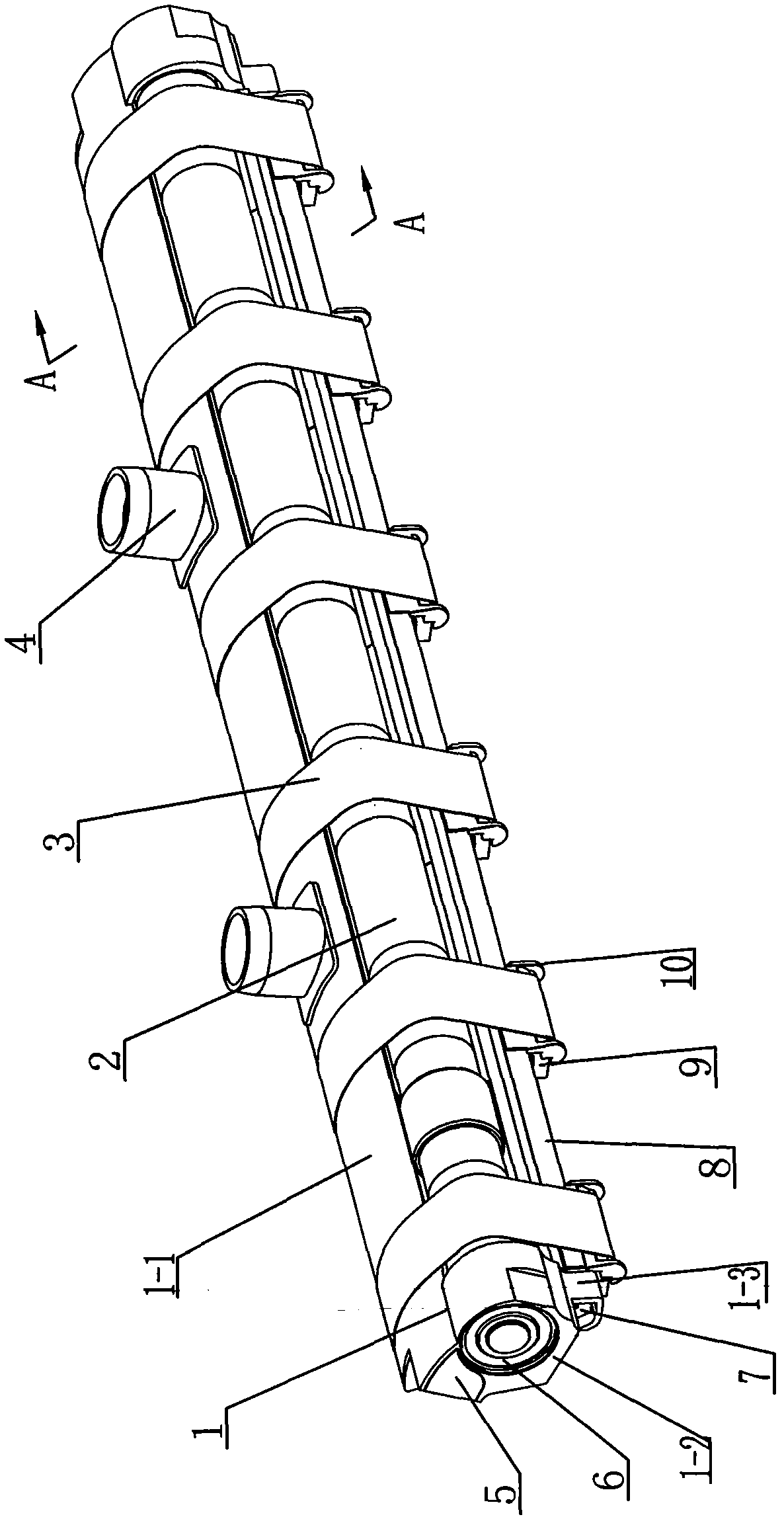
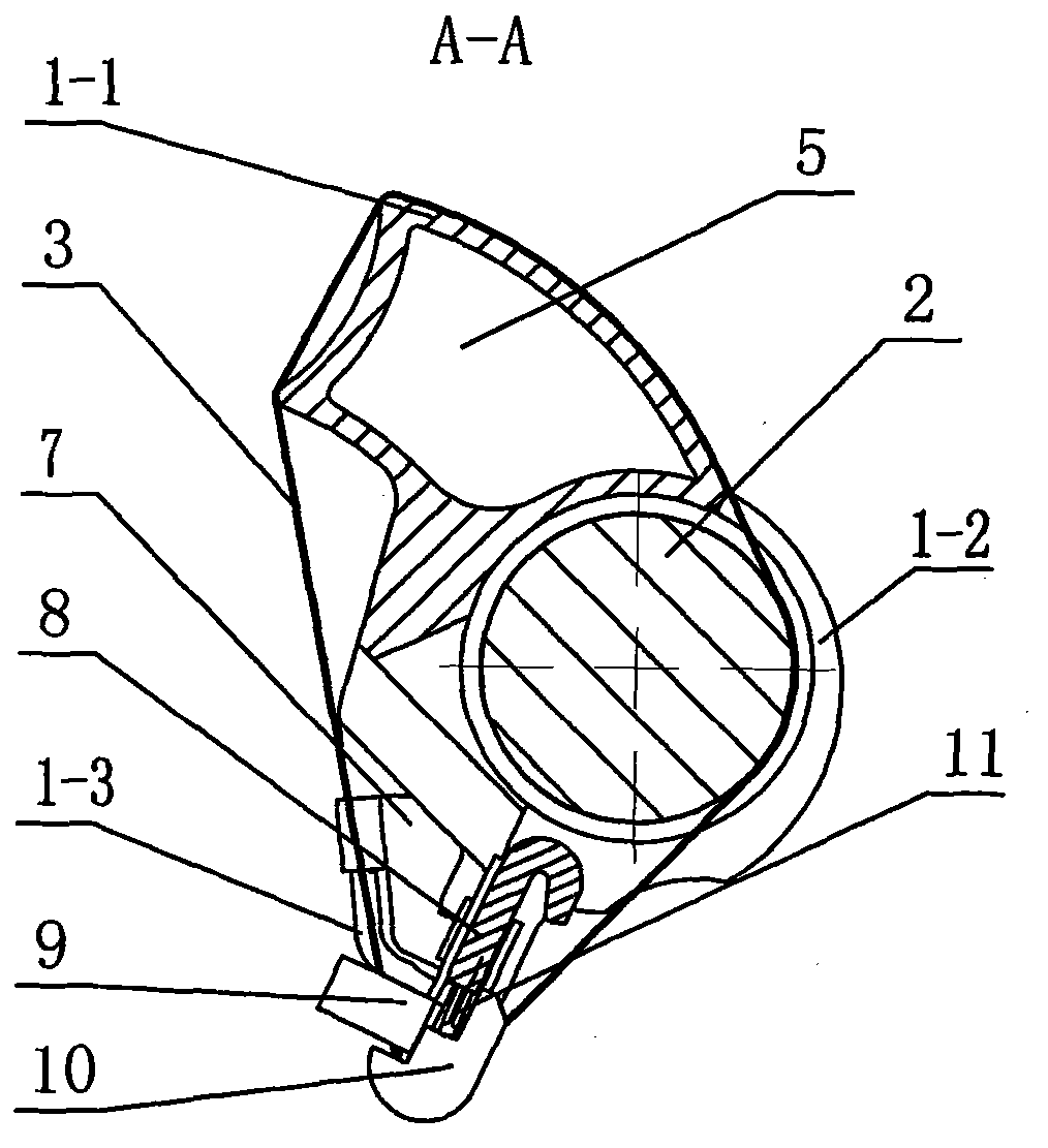
support point is far away from the clamping point of the accumulating roller and the control top roller, the tension bar is also installed on the obliquely lower side of the accumulating roller. The limit sliding seat with axial movement limit, but the tension rod must be connected to the gathering tube by inserting into the two connecting parts, which not only requires the connecting part and the gathering tube to have better manufacturing accuracy and assembly accuracy requirements, but also The production requirements for the grid ring are high, and because the tension rod is set on the oblique lower side, the tensioning efficiency of the grid ring is poor
In addition, although there is a rib on the limit slide of this structure, the rib is on the side where the grid ring is loosened during normal spinning, and is not set at the bottom of the limit slide, so the structure of this structure The stopper on the limit slide cannot effectively control the axial movement of the mesh ring, and the tension of the mesh ring after the axial offset also changes or completely breaks away from the clamping point between the accumulating roller and the control top roller so that there is no Movement, which affects spinning performance
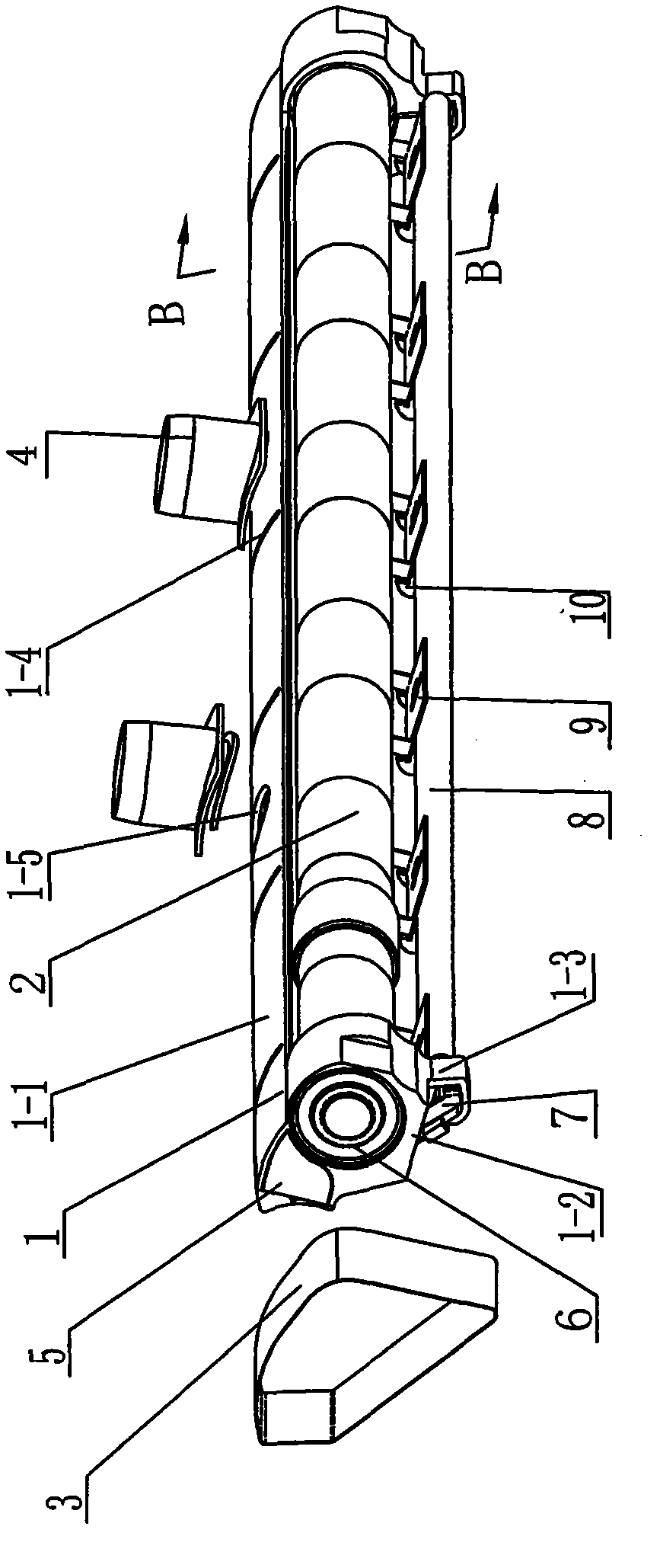
[0006] Furthermore, the tension rods of the above-mentioned several structures are all fixed on the tension frame or the connecting piece, and the tension rod cannot be overturned. Its position is relatively high, so when installing or dismounting the cleaning grid ring, the tension bracket or tension rod or the limit slide seat on the tension mechanism must be pressed one by one to install the grid ring, so the current tension mechanism has installation nets. more difficult problems

Method used


Image

  • Integrated composite spinning device of ring spinning frame
  • Integrated composite spinning device of ring spinning frame
  • Integrated composite spinning device of ring spinning frame

Examples


Embodiment Construction

[0029] See Figure 1-14 As shown, the compact spinning device of the ring spinning frame of the present invention includes a special-shaped tube 1, a grid ring 3, a compact roller 2 and a tension support mechanism. The special-shaped pipe 1 of the present invention includes a negative pressure accumulation pipe 1-1 and an end plug 5 sealed and installed at the gap 1-9 at both ends of the negative pressure accumulation pipe 1-1. The end plug 5 at the end keeps the negative pressure airflow of the negative pressure collecting pipe 1-1 from leaking, and the pipe wall of the negative pressure collecting pipe 1-1 along the guide surface is provided with at least one suction joint 4 and three suction joints communicating with the negative pressure chamber. There are more than two airflow guide grooves 1-4, and the suction joint 4 is sealed and fixed at the suction hole 1-5 of the negative pressure accumulation pipe 1-1. Inhaled into the negative pressure accumulation pipe 1-1, one ...


PUM

PropertyMeasurementUnit
angleaaaaaaaaaa

Abstract

The invention relates to an integrated composite spinning device of a ring spinning frame. The device comprises a special-shaped tube, a grid ring, an integrated composite roller and a tension supporting mechanism; negative pressure integrated composite tubes are positioned at two ends of a front tube wall on one side of a fiber whisker outlet line and provided with two extended roller supporting seats with closed peripheries, tension supporting seats are arranged below the two roller supporting seats, and the negative pressure integrated composite tubes are provided with more than two positioning surfaces; the tension supporting mechanism comprises a tension supporting frame and two positioning spring plates; the tension supporting frame comprises a tension rod and more than three limit sliding seats arranged transversely at intervals along the tension rod; the limit sliding seats are propped on the lower part of the tension rod by adjusting springs, and the bottom of each limit sliding seat is provided with a stop block; and the connecting surfaces of the two positioning spring plates are connected with the two tension supporting seats respectively, and the adjusting and installation surfaces of the two positioning spring plates are in pressing connection with two ends of the tension rod respectively. The device can improve the assembly precision, adjust the axial position of the grid ring in time and conveniently adjust the tension of the grid ring.

Description

technical field [0001] The invention relates to a compact spinning device of a ring spinning frame, which belongs to the field of pneumatic gathering devices of compact spinning machines. Background technique [0002] In order to eliminate the spinning triangle area in the compact spinning machine, a negative pressure pneumatic gathering device for fiber strand aggregation is added downstream of the main draft. It is composed of tensioning mechanism, etc. There are multiple airflow guide grooves on the tube wall of the guide surface of the negative pressure accumulation tube, and the surface of the grid ring is densely covered with air holes. On the guide groove, each airflow guide groove corresponds to a fiber whisker. Under the action of the negative pressure airflow in the negative pressure gathering tube, the hairiness of the fiber whiskers is gathered on the airflow guide groove while being transported by the rotation of the grid ring. And effectively reduce the spinni...

Claims


Application Information

Patent Timeline
Patent Type & Authority Applications(China)
IPC IPC(8): D01H5/72D01H5/56
Inventor 崔桂生胡文君
Owner 常州市同和纺织机械制造有限公司
Why Eureka
Try Eureka