Concrete delivery tube and preparation method thereof

A technology for a concrete conveying pipe and an outer pipe, which is applied in the field of concrete conveying pipe and its preparation, can solve the problems of large flow channel resistance, easy to cause pipe blockage, changes in chemical composition and performance of surfacing alloy, etc.

Inactive Publication Date: 2011-04-27
湖南三一中阳机械有限公司
View PDF7 Cites 27 Cited by
  • Summary
  • Abstract
  • Description
  • Claims
  • Application Information

AI Technical Summary

Problems solved by technology

The deficiencies of the prior art are: (1) the inner surface of the S pipe obtained by surfacing welding is rough, the flow channel resistance is large, and it is easy to cause pipe blockage; (3) The production efficiency of surfacing welding is low and the production cost is high; (4) The controllability of surfacing welding process is poor, the welding operation is difficult to quantify, and it is easy to cause changes in the chemical composition and performance of the surfacing alloy, which is difficult to guarantee The thickness and uniformity of the welding layer; (5) In addition, the parts most prone to wear at both ends of the S pipe may be shortened due to insufficient welding; (6) The pipe wall blank is relatively thick, so the thickness of the surfacing layer is limited, which greatly affects the Service life of S tube
[0005] In the prior art, various preparation methods of composite pipes have been disclosed, such as preparing straight composite pipes by means of interference fit between the inner pipe and the outer pipe, and preparing bent pipes by thermoplastic deformation, but these methods do not Suitable for preparing S pipes for conveying concrete
The main reasons are as follows. Since the S tube has two variable cross-section bends, the inner tube and the outer tube cannot be combined by interference fit.
In addition, it can also be considered to prepare the composite conical tube by interference fit first, and then heat and bend it to obtain the S tube, but the S tube prepared by this method also cannot meet the requirements, because the composite conical tube is bent and formed twice. Inconsistent deformation of the inner and outer tubes, so bends can easily fail

Method used


Image

  • Concrete delivery tube and preparation method thereof
  • Concrete delivery tube and preparation method thereof
  • Concrete delivery tube and preparation method thereof

Examples


Embodiment approach

[0038] According to the present invention, when preparing the delivery tube, various methods can be used for preparation, wherein, the first embodiment of the delivery tube preparation method provided by the present invention includes:

[0039] provide an inner tube;

[0040] A first part of the outer tube and a second part of the outer tube are provided, and the first part of the outer tube and the second part of the outer tube are attached to the outside of the inner tube and connected to obtain an outer tube compounded on the outside of the inner tube.

[0041] Wherein, when connecting the first part of the outer tube and the second part of the outer tube, welding is preferably adopted. As for the components of the outer tube, it may include a plurality of outer tube parts whose cross-sections are arc-shaped, and the cross-sections of the plurality of outer tube parts enclose a circle as the outer tube. According to the present invention, after the multiple components of t...

Embodiment 1

[0048] Wear-resistant cast iron is selected as the inner tube material, and the inner tube is obtained by one-time casting. The composition of the inner tube is calculated by weight percentage: 3.1% of C, 1.2% of Si, 1.9% of Mn, 0.035% of S, 0.036 of P, 2.8% Mo, 1.9% Cu, 2.4% Ni, and the balance is Fe.

[0049] Low-alloy steel is selected as the outer tube material, and its composition is calculated by weight percentage: 0.375% C, 0.35% Si, 0.65% Mn, 0.9% Cr, 0.035% S, 0.036 P, and the balance is Fe .

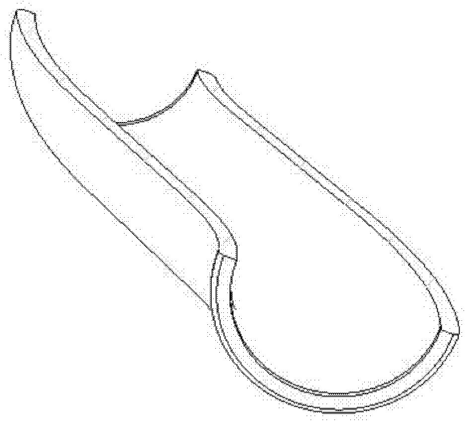
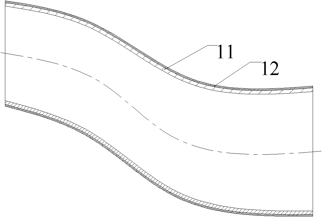
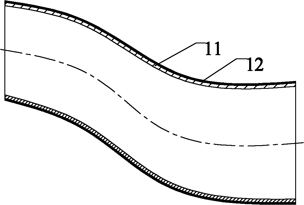
[0050] The half-pipes of the two outer tubes are prepared by molding, such as figure 1 Shown is a schematic diagram of one of the half-pipes. Then the two half-pipes are clad on the outside of the inner pipe and welded together to form a variable-section S pipe, such as figure 2 As shown, the variable-section S-tube includes an inner tube 11 and an outer tube 12 compounded outside the inner tube.

[0051] The heat treatment process is: 980℃×3h normalizing treatment. Then ...

Embodiment 2

[0054] High-speed steel is selected as the inner tube material, and its composition is: 0.98% of C, 0.30% of Si, 0.16% of Mn, 8.5% of Mo, 3.7% of Cr, 1.9% of V, 1.5% of W, 0.025% of S, 0.028% of P, and the balance is Fe. The material of the inner tube is molded out of the desired arc of the S tube by a hydraulic press to form two inner tube half-pipes, both of which have an inner diameter of 20 mm.

[0055] Carbon steel is selected as the material of the outer tube, and its composition is calculated by weight percentage: 0.5% C, 0.6% Si, 0.9% Mn, 0.035% S, 0.036 P, and the balance is Fe. The material of the outer tube is molded out of the arc required by the variable-section S tube through a hydraulic press to form two outer tube half-pipes,

[0056] The two inner tube half-pipes and the two outer tube half-pipes are welded together to form an inner tube and an outer tube surrounding the inner tube.

[0057] The heat treatment process is: quenching 1190. ℃ × 2 hours, temper...


PUM


Abstract

The invention provides a concrete delivery tube, which has at least two bent parts and comprises an inner tube and an outer tube compounded outside the inner tube, wherein the outer tube at least consists of an outer tube first part and an outer tube second part; the shapes of cross sections of the outer tube first part and the outer tube second tube are circular arcs; the outer tube is formed by connecting the outer tube first part and the outer tube second part; and the wear resistance of the inner tube is higher than that of the outer tube, and the roughness of the outer tube is higher than that of the inner tube. Compared with the prior art, a high-priced surfacing welding process is not required to improve the wear resistance of the inner surface of the delivery tube, and with the composite tube having the inner tube with high wear resistance and the outer tube which is compounded outside the inner tube and has high roughness, the concrete delivery tube meet the requirements on wear resistance and mechanical strength.

Description

technical field [0001] The invention relates to a concrete conveying device, in particular to a concrete conveying pipe and a preparation method thereof. Background technique [0002] The concrete delivery pump truck / trailer pump is the key equipment for the construction of high-rise buildings and other buildings to deliver concrete. The S pipe used on the concrete delivery pump truck / trailer pump is a key component. The S pipe is to have two directions roughly The conveying pipe at the opposite bend, which is roughly S-shaped when viewed from the side, is a concrete conveying component well known to those skilled in the art. As a key component that affects the service life and stability of the pump truck, since the inner surface of the S pipe is in direct contact with the concrete, it is continuously washed by the concrete during the working process, so higher requirements are put forward for the performance of the S pipe. In general, because the inner surface of the S tub...

Claims


Application Information

Patent Timeline
Patent Type & Authority Applications(China)
IPC IPC(8): F16L9/00F16L9/02F16L57/06E04G21/04
CPCF16L57/06F16L9/02F16L43/001
Inventor 秦建军张琦吴星荣
Owner 湖南三一中阳机械有限公司
Why Eureka
Try Eureka